
DIY 3D Printer Enclosure – Repurposing the IKEA LACK Table
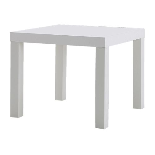
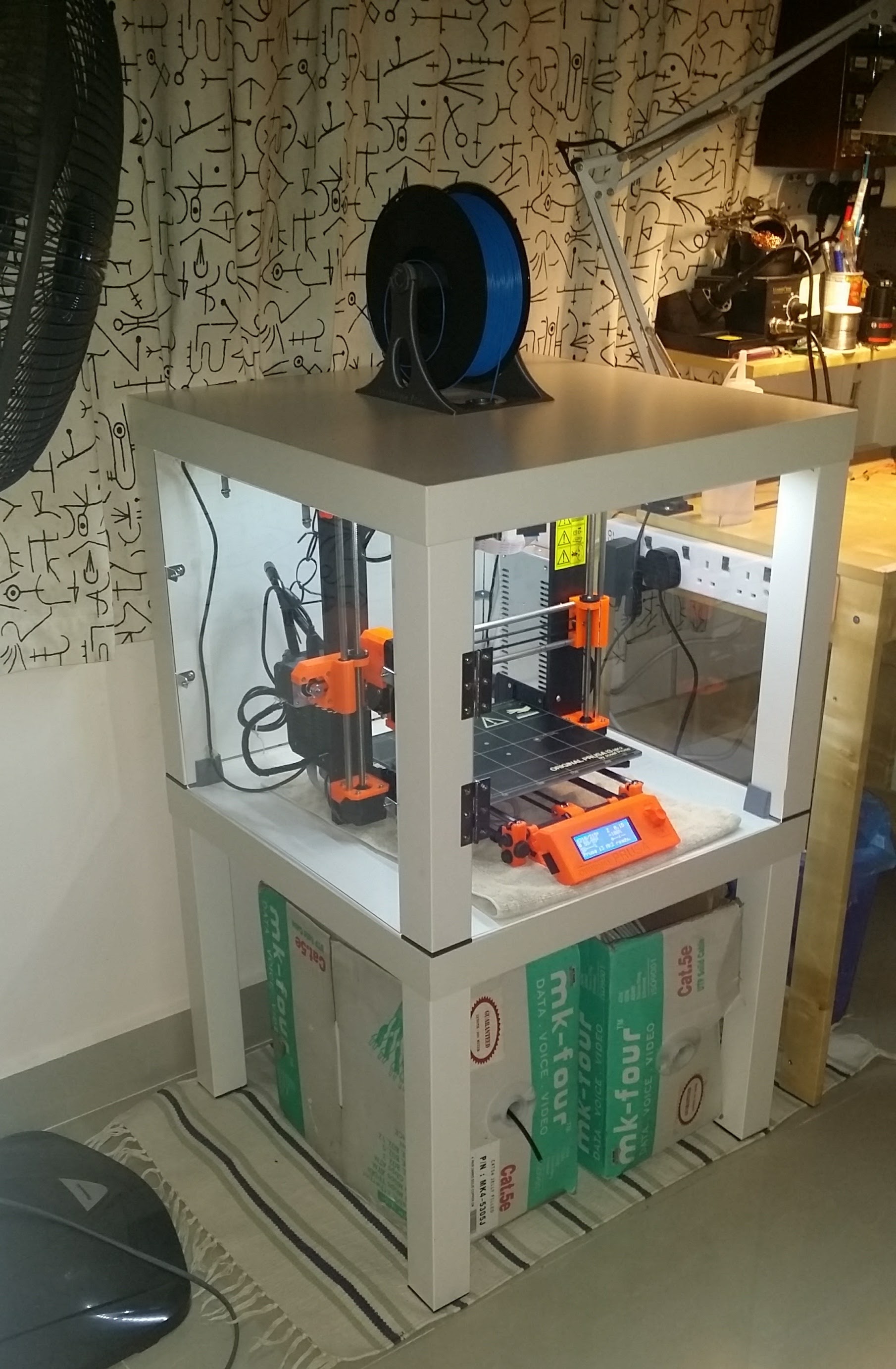
I decided to re-purpose the IKEA LACK coffee table into an enclosure for my 3D printer. It’s a well known hack that when stacked, among other things, the LACK is the perfect size for the Original Prusa I3 MK 2 printer (and most i3-style printers), and I already had two of IKEA LACKs in the house (and even if I didn’t, they’re currently going for MYR29.90 which is a pretty cheap way to get a basic structure started).
Filament Holder and LACK support brackets
There isn’t room for the filament spool that sits on top of the printer when using with a LACK Enclosure. Instead you need to put the filament on the tabletop above the printer. For this to work, I needed to print a replacement filament holder, as the supplied one is designed to clip to the top of the printer’s frame.
I found a suitable design on Thingiverse (https://goo.gl/Pue9nV). This was actually quite large (compared to the stuff I’d printed so far) and took a whole day to print. I’ve not spent much time tuning my printer yet and it was the first time I had to print something with supports (the spindle, being cylindrical needed supports. In hindsight, I should have just rotated it and printed it vertically instead … might re-do this). As a result the spindle had some rough edges and did not rotate in the holder easily, but that isn’t strictly necessary … the spool itself will rotate around a non-moving spindle.
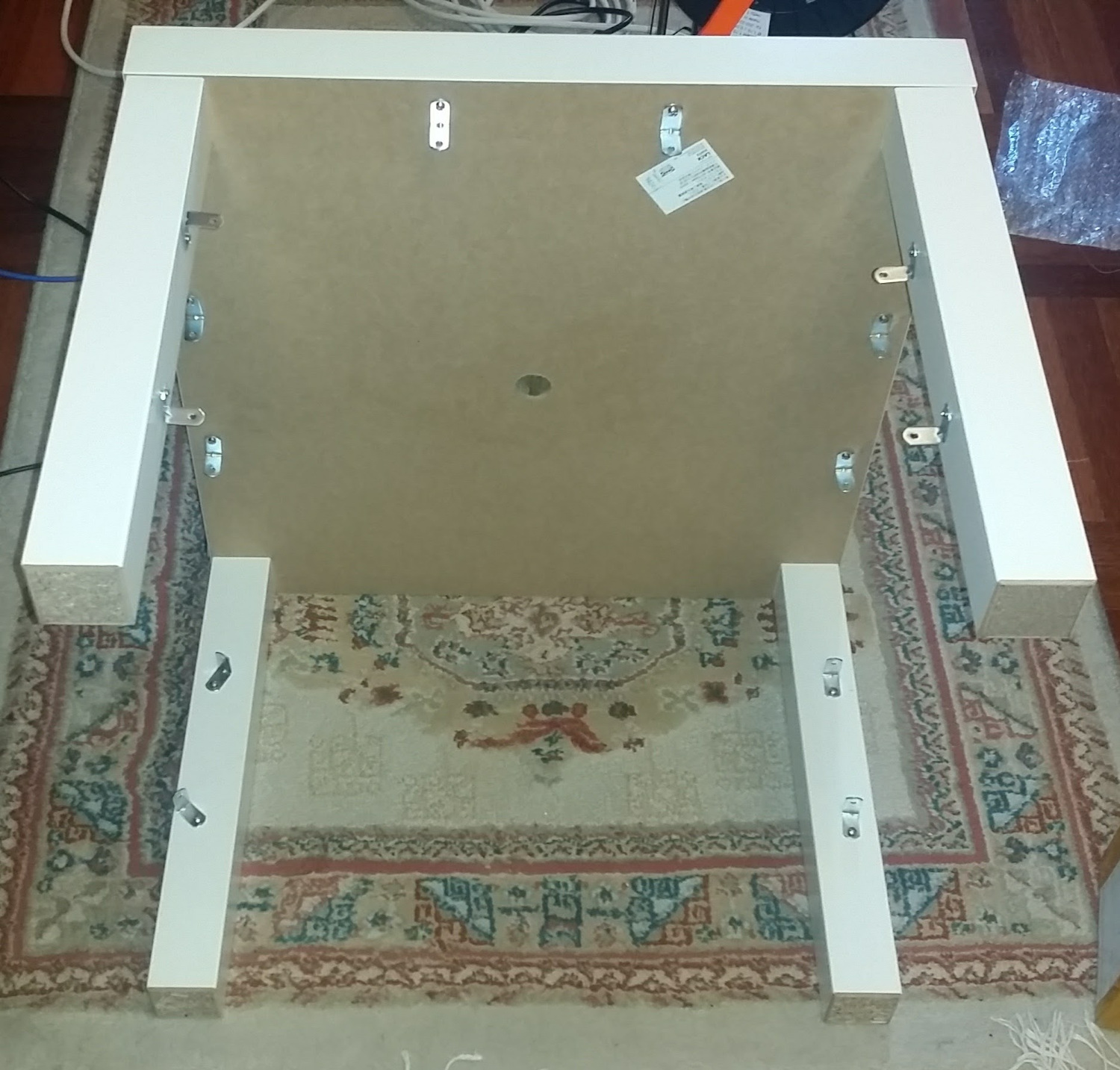
I also printed some support brackets for stacking the LACK tables. I didn’t need to raise the upper table, but I wanted some way to ensure it would remain securely in place. I also wanted to be able to easily lift the upper table in case I needed better access to my printer for maintenance. I found this design on Thingiverse that suited my needs (https://goo.gl/Pue9nV). It screws into place on the lower table, and has supports on the inner side of the legs of the upper table, to ensure that the upper table doesn’t slide around.
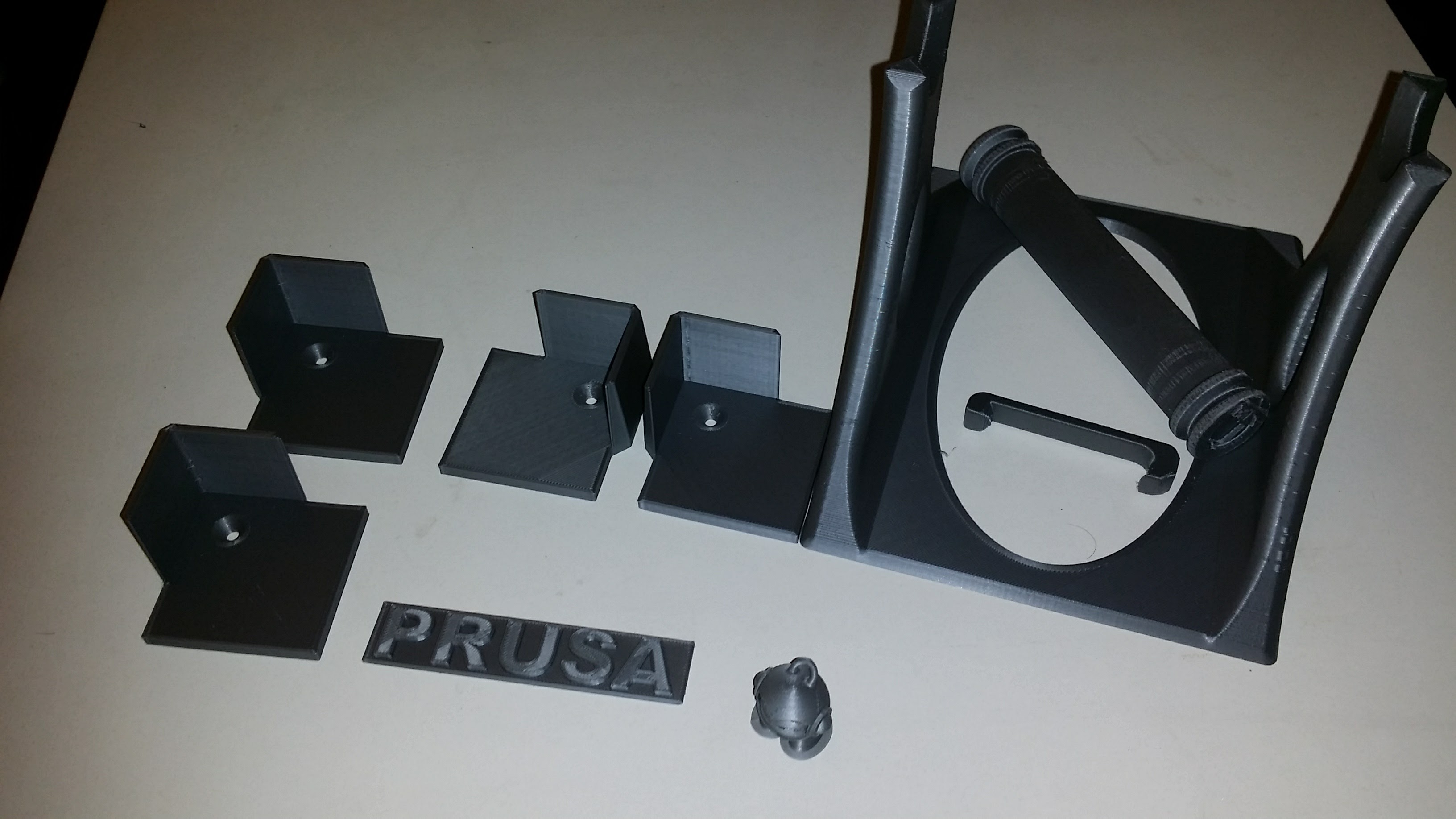
Here’s the spool holder and the LACK brackets I printed (plus the test prusa logo and robot from the SD Card):
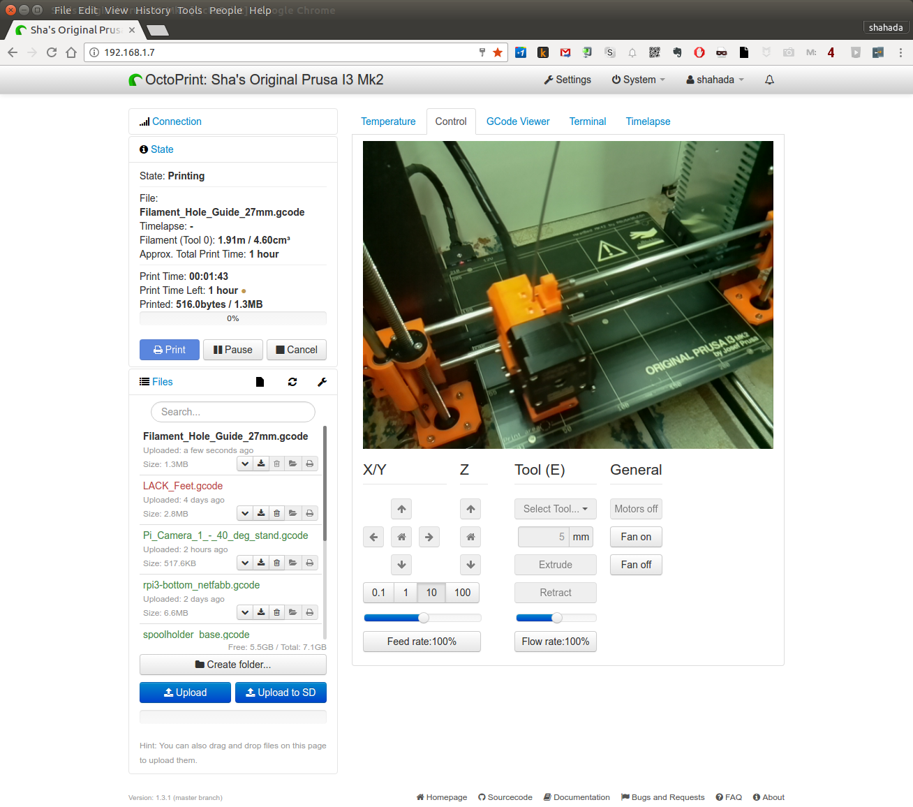
Filament Hole
Having the printer inside an enclosure with the spool holder outside necessitates a hole in the table surface to get the filament through to the printer.
I had purchased a hole cutter drill bit some year’s back, and now finally I got to put it to use. I measured the center point of the table (you’ll want to have the printer centered on the table to maximize the space for the moving Y-carriage, which means the extruder is around the center of the table too, so that’s where the filament needs to drop into), drilled a pilot hole and set the hole cutter to work.
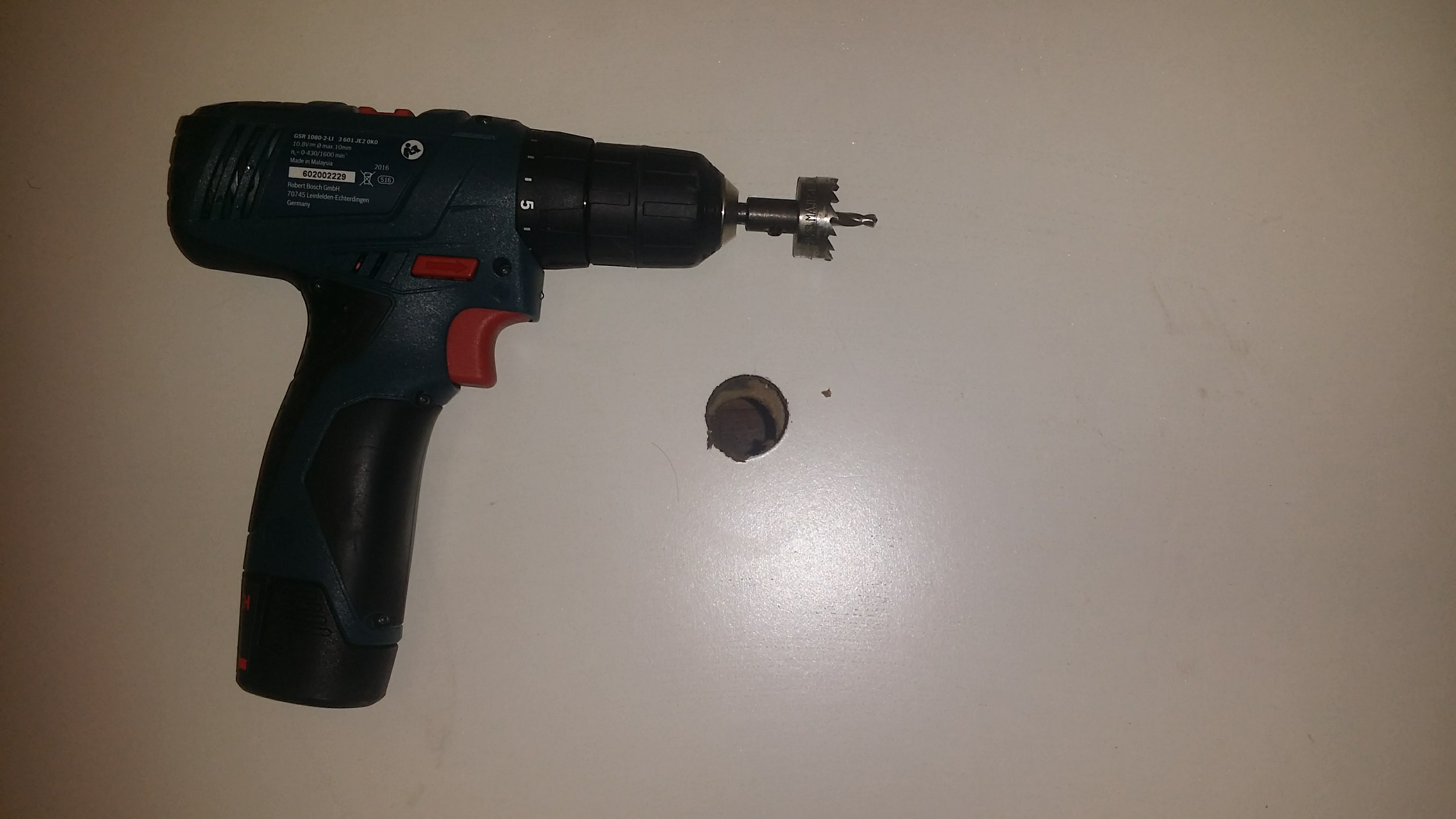
Did I mention how much I hate MDF? The fibre dust inside the LACK is really awful, and it’s more like LOW density fiberboard. I cleaned it up as best that I could with a wet cloth afterwards. The cutter only ended up cutting one side of the surface, as the bit wasn’t deep enough to reach the other end. Fortunately, since I had drilled a pilot hole straight through, it wasn’t much of a problem to cut the a similar hole from the other side and have it line up.
I decided I needed some sort of plastic piece to line the hole to make it easier for the filament to go through, and also to protect the sides of the hole from chipping. I measured the diameter of the hole at around 27.8 mm (although the hole cutter said 28mm). The LACK table is 50mm deep. Some sort of cylinder with a brim perhaps?
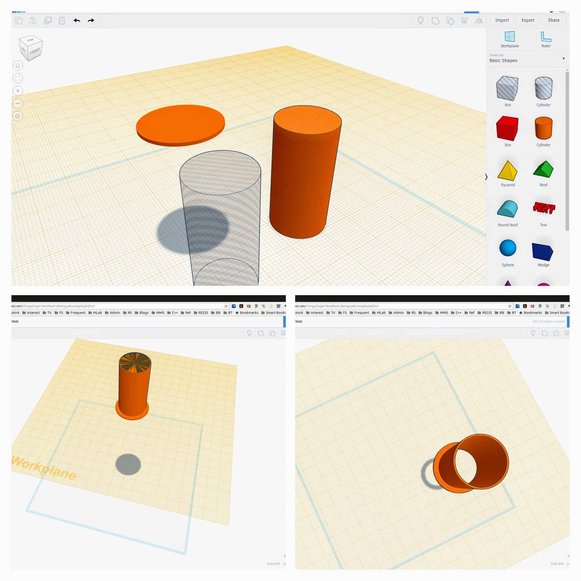
I drew three cylinders in TinkerCAD, one 27.8mm for the outer cylinder, and the other 26.3mm (1.5mm less) for the inner cylinder, and another 35mm for the brim. I increased the “sides” to the maximum of 64 to get as smooth a circle as possible. I set the two cylinders to 55mm high, and the brim to be 2mm high. The inner cylinder was set as a hole. I set the workplane to the bottom of the brim, center-aligned all three and dropped all three to the workplane level. Finally I grouped all three objects, which causes TinkerCAD to apply the hole to the solid objects.
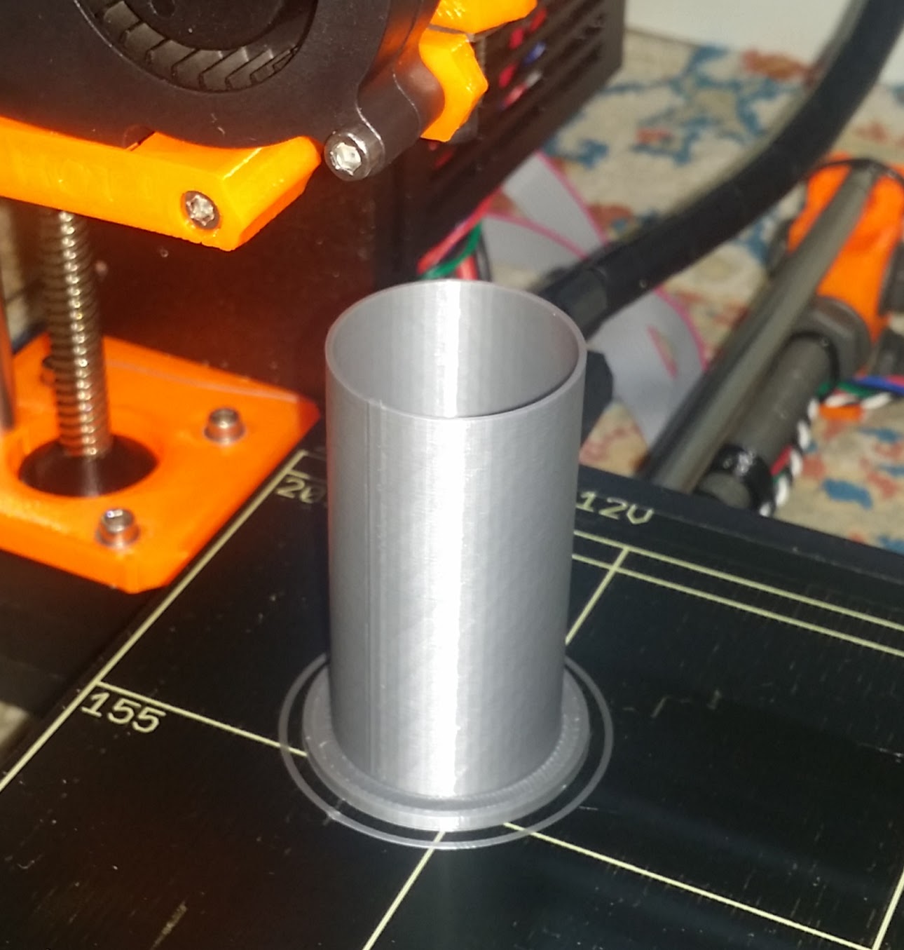
It printed out beautifully …
… only for me to discover that the upper and lower holes that I had made on the LACK table weren’t aligned well, despite sharing the same pilot hole (probably I didn’t drill down straight). I had to use a file to trim off a side of the lower hole for the filament guide to fit in (more MDF dust!).
Pi Case
I planned to mount the Raspberry Pi at the top of the enclosure, so it won’t be visible from outside. I found an excellent one on thingiverse (https://goo.gl/a8QAxA) which had tabbed “feet” with mounting holes.
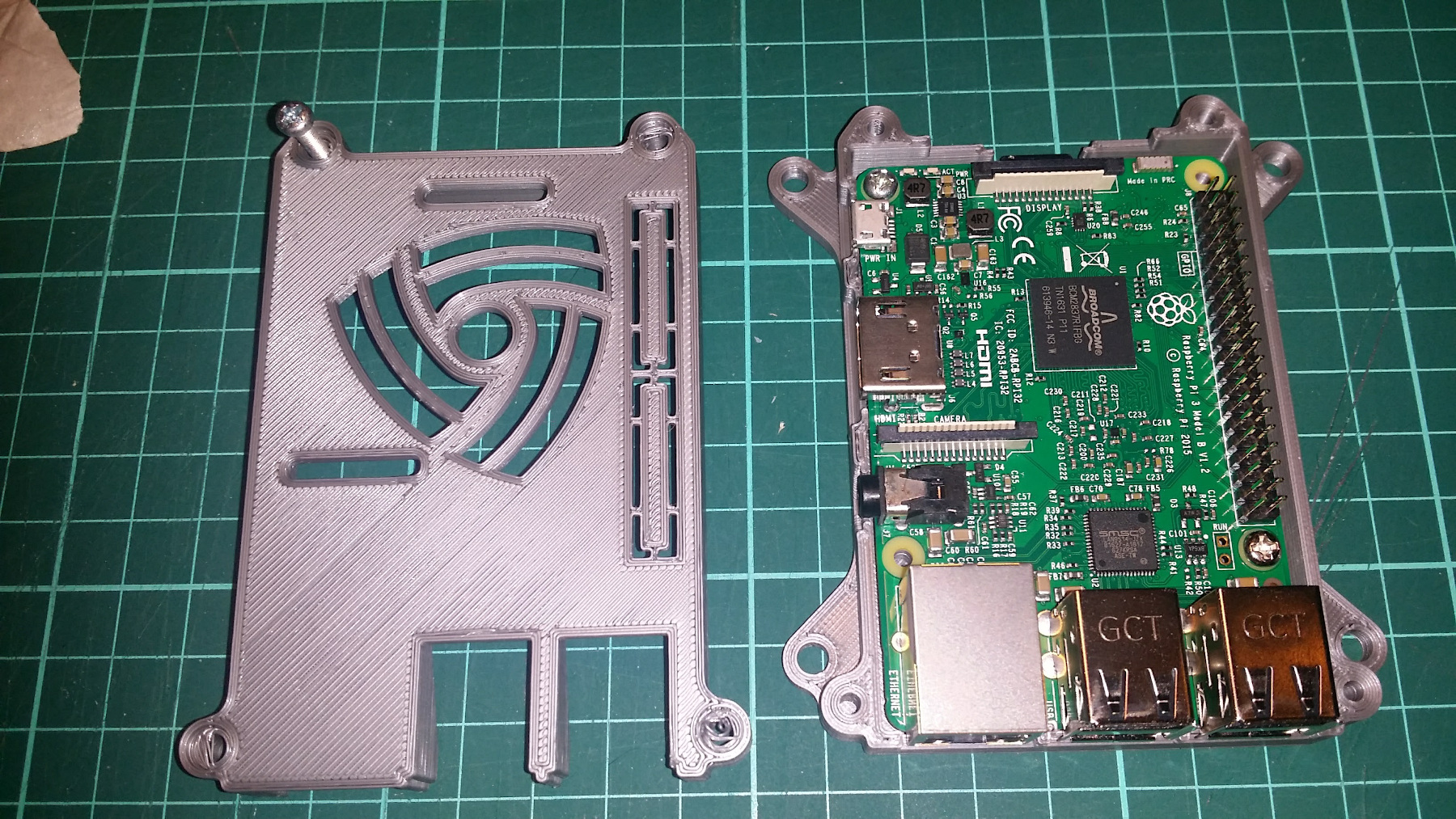
The screw holes to mount the Pi were too big for the standard M2.5 screws that the Pi uses. Fortunately the Pi 3’s mounting holes have a rubbery/plastic rim around the hole and you can force a bigger screw into it, without risking shattering the PCB itself. I’m not sure if the holes are actually threaded but I screwed in two M3X10s and they seemed to hold tightly.
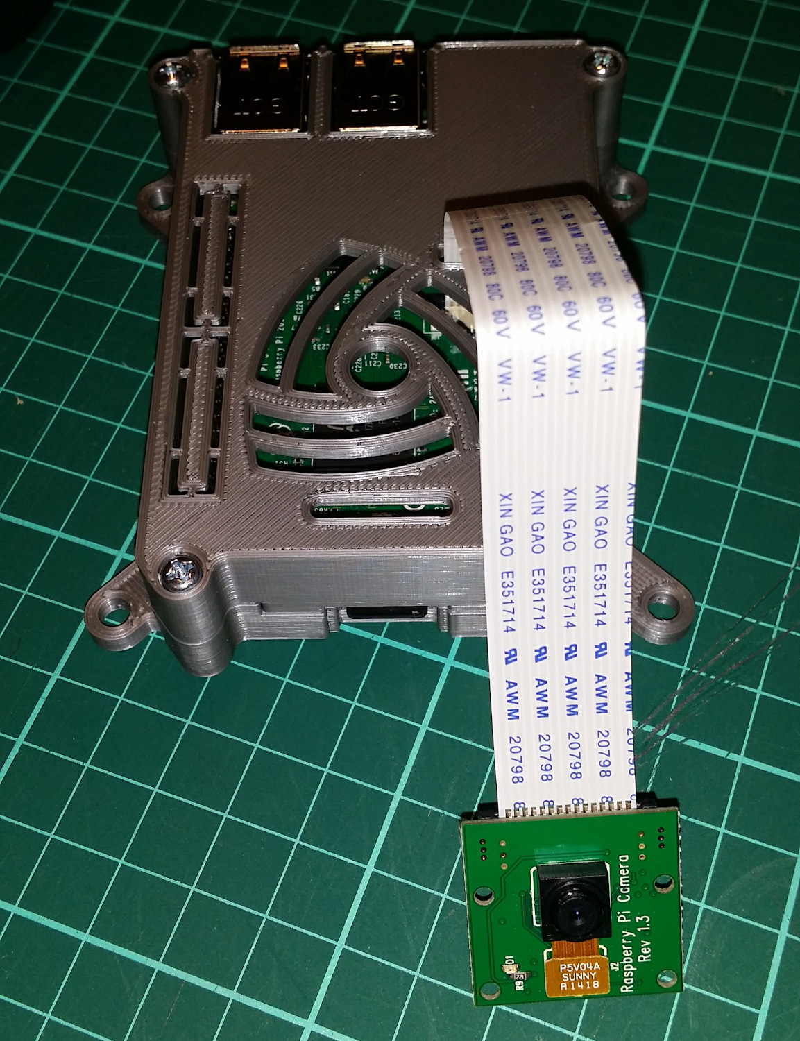
For the casing screw itself, I used M3x16s and they held the two parts well. The case features a slot so the ribbon cable for the camera can exit properly.
To give a neat appearance I mounted the Pi enclosure to the underside of the LACK table. This would be the inside “ceiling” of the enclosure, so would not be visible from outside unless you knelt down in front of it. Given that most of the inside of the LACK is rather low density fiberboard that won’t grip screws well, there was no point using long screws to mount stuff — I went with short wood screws that depended on the 3mm-ish outer shell of the LACK’s surface to hold stuff in. This seemed to work quite well provided you stop turning the screws in when they’ve reached their limit.
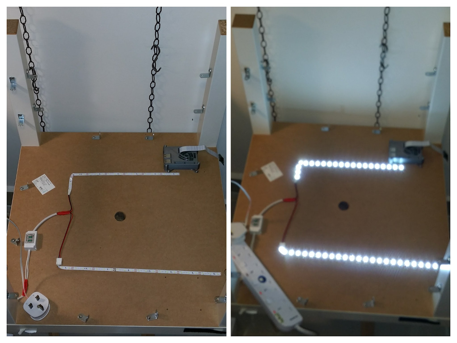
LED Lighting
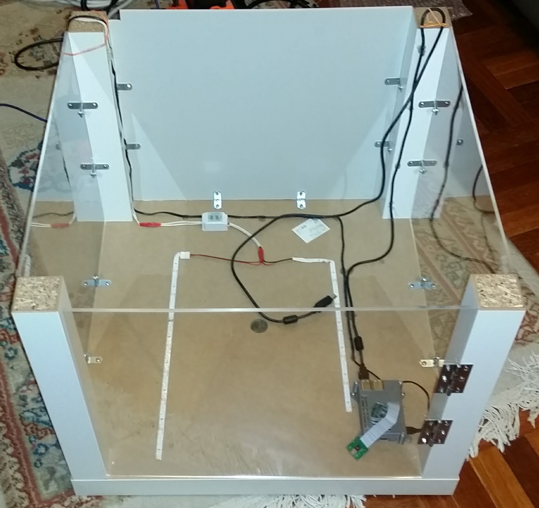
I planned to have the insides lit using LED strips (https://goo.gl/cjlTvm), so I cut off two lengths and soldered the wires in parallel to the output of a small LED transformer (240VAC to 12V 3-5W https://goo.gl/RRgGC6). I then soldered the input end of the transformer to a length of electrical cord and attached a 3-pin plug. Powered it on and it lit up ok, so I stuck the LED strip to the underside of the table and fixed the wires down using hot-melt glue.
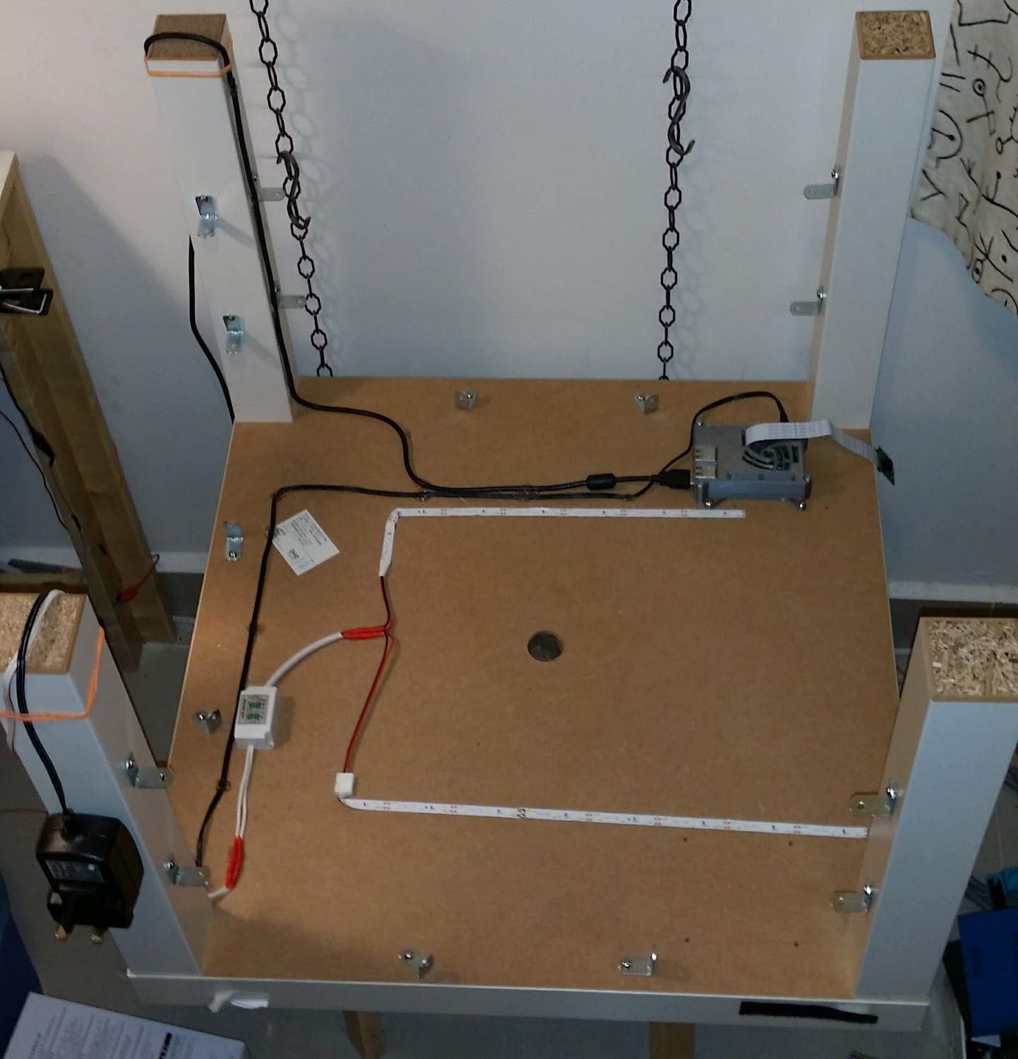
Internal Wiring
I used hot-melt glue to attach the Pi’s USB cable, Power cable and Ethernet Cable down. All of these ran to the rear-right leg of the table.
Pi Camera Stand
Next up, was to make a stand for the Pi Camera. This is connected to the Pi via a ribbon cable, and needs some sort of mount to hold it in place at the correct angle facing the printer. I planned to hack something up in TinkerCAD … just a rectangle base and a triangle shape should do.
I held it manually to get a good angle, and it turned out to be somewhere on a plane around 50 degrees from the horizontal. The camera board is around 25mm x 25mm. TinkerCAD doesn’t seem to let you set the angle of a triangle, but rather you can specify the height and width, and it draws the hypotenus side automatically. So …
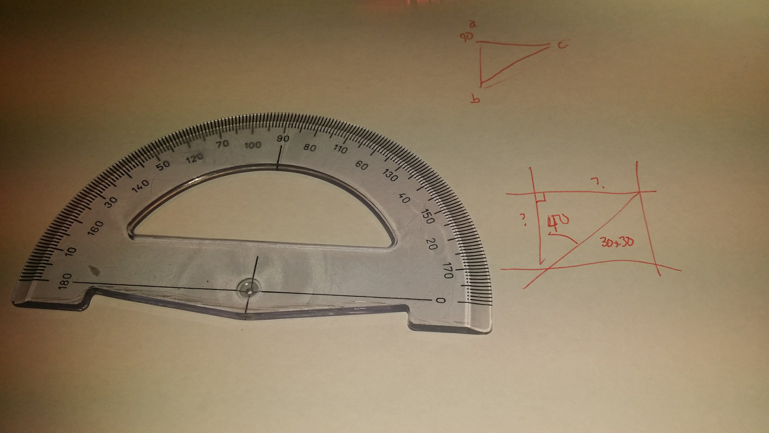
Darn, there really is a use for all that trigonometry we had to we’re supposed to learn back in school. I declared it was sufficient to know the concepts and as intelligent human beings we should use all the tools at our disposal and ended up here:
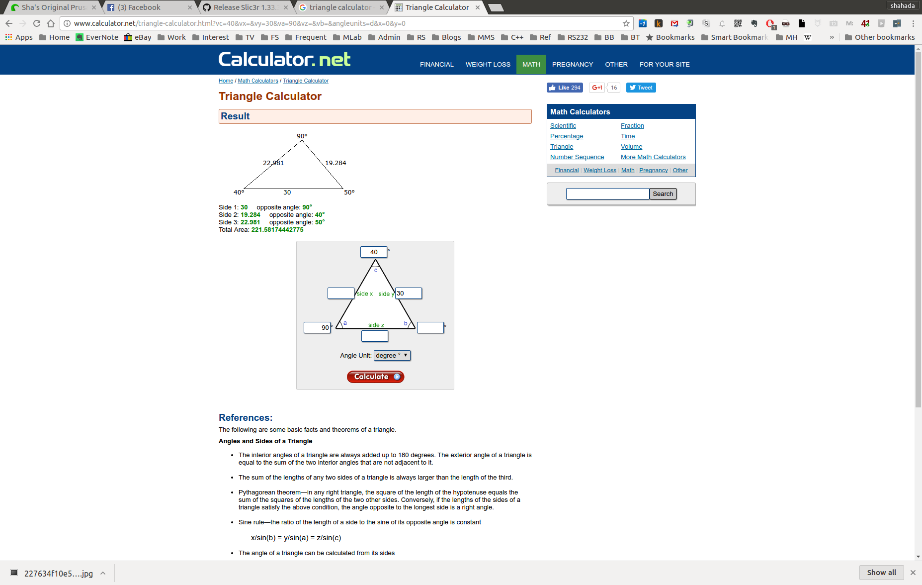
Taking the lengths of the sides from there, I sketched this up in TinkerCAD:
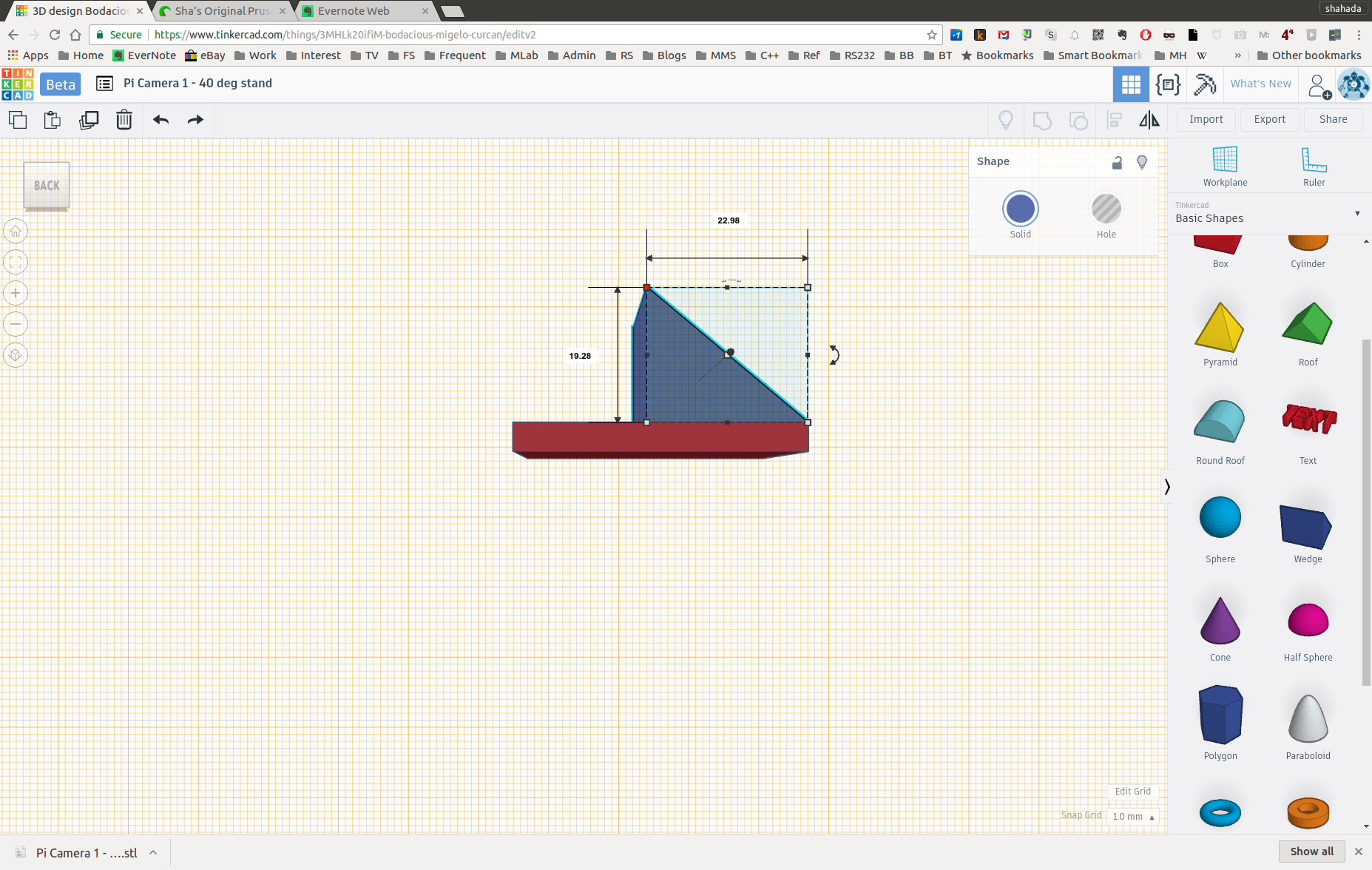
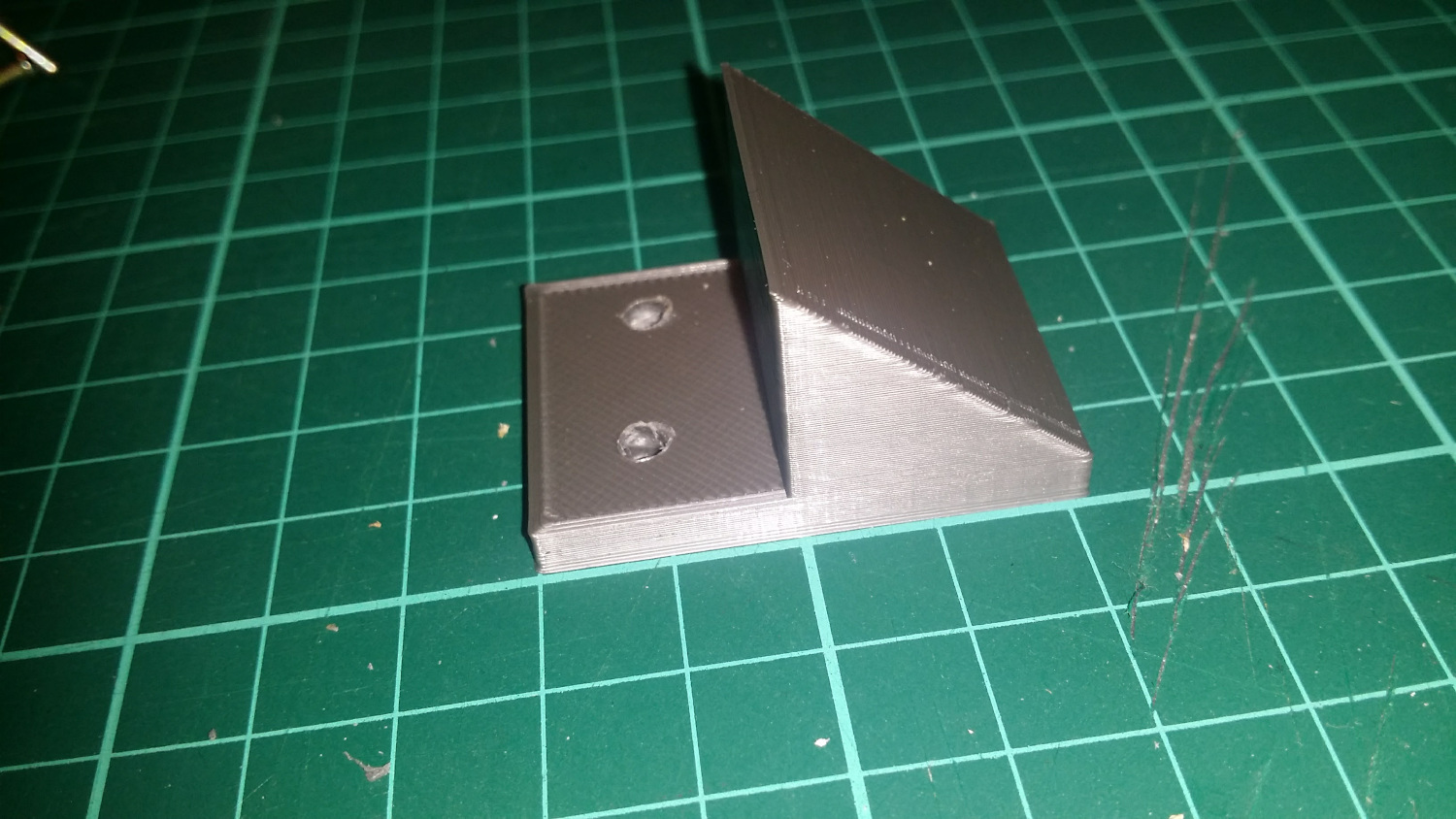
I made the camera mounting surface side bigger (30mmx30mm) so I could drill screw holes without risking them being too close to the edge. I found a useful template for the camera here (https://goo.gl/Oy9cVP), only to discover that the camera uses 2mm screws …! Yet another bloody size I don’t have! Cursing, I ordered 100 pcs of M2x10mm self-tapping screws off ebay (https://goo.gl/tn0WCg), and used some double sided tape for the time being.
I realised I also forgot to design in mounting holes for the bracket itself, so drilled two 3mm holes into the plastic. Here’s the printed result:
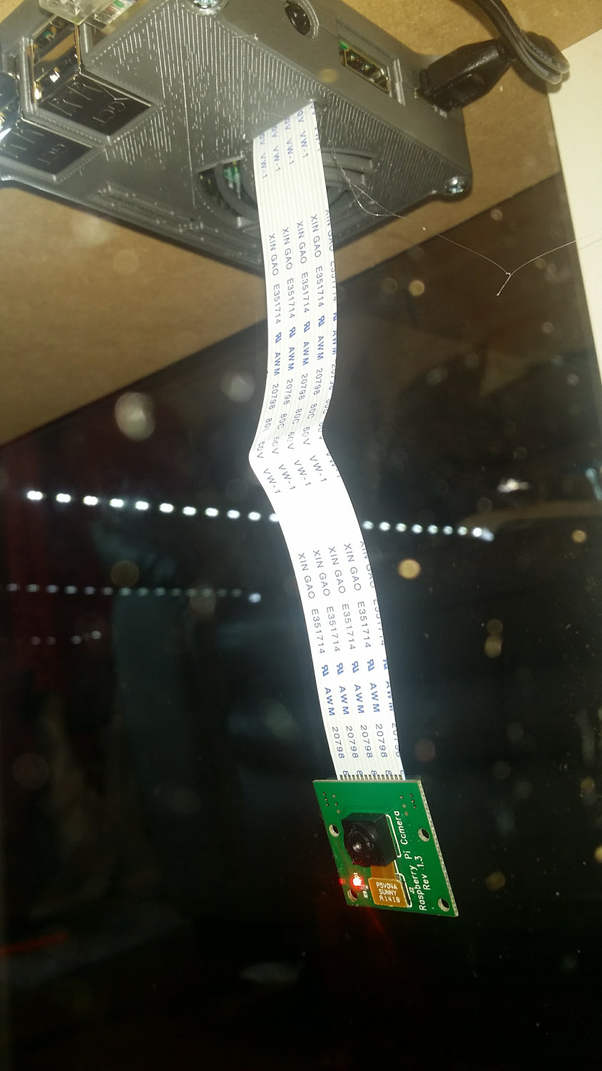
Here’s the mount in place:
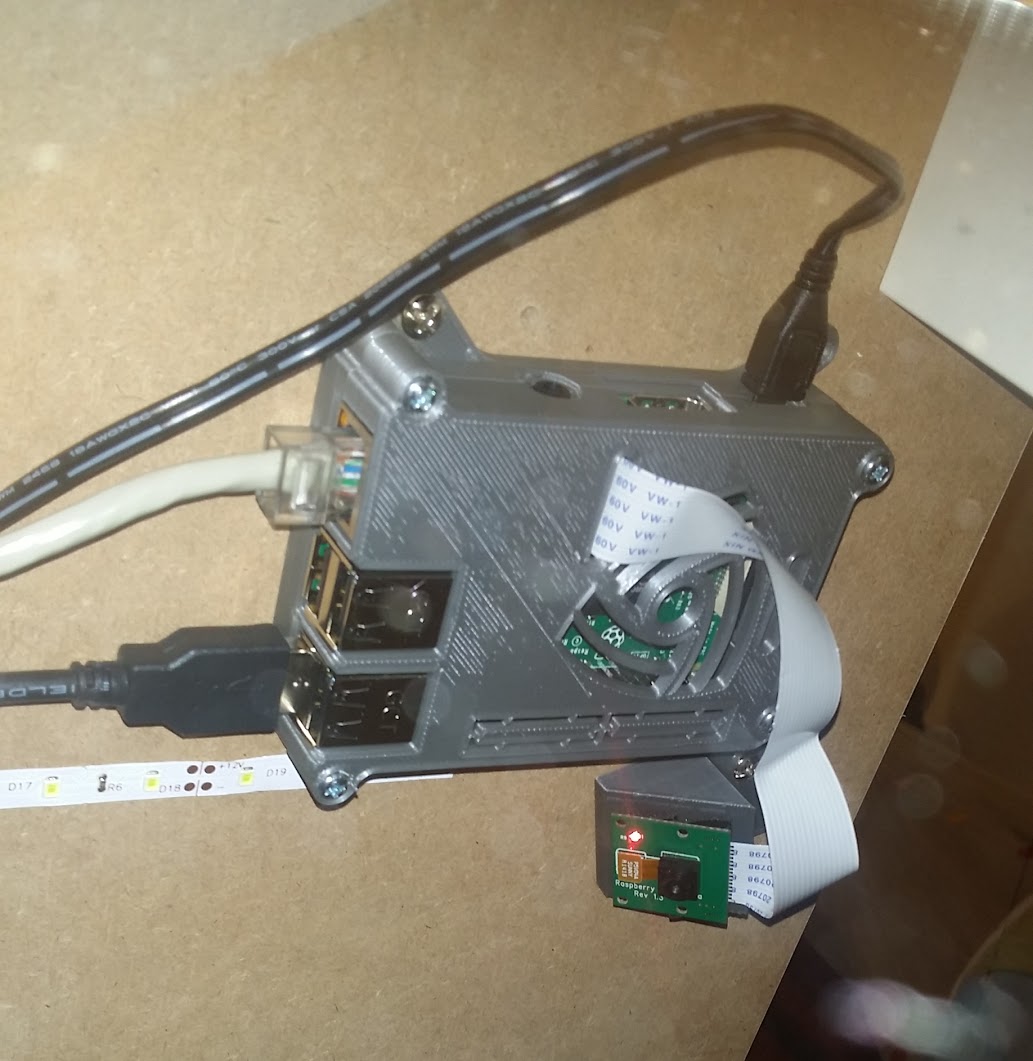
And this is the view:
The field of view of the Pi Camera isn’t that great so this is about as good as it gets. It’s sufficient for monitoring purposes. Having the camera mounted solidly to the table frame does help a lot in keeping the image stable.
Windows
To show off the printer I of course need transparent windows. I decided on using acrylic as the material. Glass would probably be nicer but would be harder to mount, as I’m not too familar with drilling into glass. I measured the space under the sides of the LACK table to be 440mm x 400mm.
Where does one order acrylic from? I’ve bought small sheets from the Art Friend (https://goo.gl/wQKmmC) before, but for any thickness beyond 2mm it’s hell to cut. And being the display windows I would need them to be cut very “cleanly”. So it was best to leave this to the professionals and their laser-cutting CNC machines.
I found a website (http://www.acrylicmalaysia.com.my/) for a local signage maker, Cenad Art , that supplies materials online, and they have a wide selection of acrylic materials and sizes. I wanted it to be thick enough that it would be stable, but at the same time not too heavy to work with, and ended up choosing 4mm acrylic (In hindsight: Go with 5mm!). The nice thing here is that if you key in the dimensions into their online store (https://www.cenadart.com.my/onlinestore/Â they give you the price online immediately … which came up to RM39 per side. I don’t know if this is expensive or cheap, since it’s my first time buying acrylic of this size but since I was ok to pay this price I proceeded.
To keep the costs down, I decided to get acrylic for just the front and sides, and use white PVC board for the rear. This would also make it easier for me to cut access holes into the enclosure, as the PVC board is much friendlier material to work with.
Unfortunately, shipping from Cenad Art’s store came up to MYR71 … more than half of the total of the acrylic itself, and shipping is always included when ordering from their online store. I contacted them (michelle@cenadart.com) and they had no issues with me collecting them, and gave me a quotation for just the acrylic material within 24 hours. I banked in the money and they had the items ready for collection by the next day … which was a state public holiday, but they were still open, so I drove over and picked up the stuff. Cenad Art is located in a swanky industrial estate at the southern end of Puchong, near Cyberjaya. Items were ready at the reception counter so I was in and out in less than a minute.
btw: I also found another source for acrylic which is Kar Seng Signs and Material Sdn Bhd (http://www.signsmaterial.com.my/) in Sungai Besi. They don’t have an online store and I didn’t get a reply to my email asking for a quote, so I guess you’d need to call them or drop by their place to find out more. I believe they’re focused more on material supply.
On the way back I stopped at Art Friend at The Curve and picked up a large 450mm x 600mm PVC board for MRY16.30. I cut this to size with a regular box cutter (I love working with PVC board!). I also made a small square hole at the corner for cables to get in.
Next was to prepare the mounting. I had bought some small L-brackets from Mr DIY some time back, so I placed the windows in position and marked the position for the L-brackets and screwed them into place. I placed two brackets on the top, left and right side of each window spaced about a third in (in hindsight, I think it would be better to have used three brackets, at the two ends and center, as it would ensure the corners are exactly flush with the LACK’s legs).
I then marked the position of the holes on the acrylic, and set about drilling the 3mm mounting holes. I have a drill press at home which made the job and absolute doddle. I then peeled off the adhesive protection layer from the acrylic. btw: the acrylic Cenad Art supplied is the original Plexiglass brand, and was of quite high quality and very clear (it’s also warranted not to yellow for 30 years or something like that). I’m quite happy with it and will gladly buy from them again. I believe if you need specific shapes and holes made they can also accept your soft-copy and laser cut them.

For the front door I used a cheap door hinge I got at Ace Hardware (cheapest one I could find at MYR2.12). It turned out that to have the glass flush with the front surface of the LACK, I needed to put the hinge on the outside, where it’s visible, as opposed to the inside. Either that or I don’t know how to mount a hinge properly. Anyway, having it on the outside does give a “antique treasure chest” kind of look.
I wanted a magnetic door catch so that the door will stay shut … but did not find this in any of the shops I checked at. So I ordered them on eBay (https://goo.gl/mprdKu) which means it’ll be a few weeks till I get the door closing mechanism sorted out. I’ll sort out a door handle then as well.
Final Assembly
This effort was preceded by a massive clean up of my utility room, with the result that while there’s now less things in the utility room, there’s a lot more stuff in the corridor outside that needs to be dealt with at some point in time.
I attached the LACK mounting brackets I had printed to the lower table. It required a bit of tugging to get the upper LACK into the slots in the brackets. With the brackets the LACK’s legs sit perfectly square, and I suspect they were not when I attached the windows. I had to loosen some of the mounting brackets to get it aligned. Still, a tight fit is a good fit.
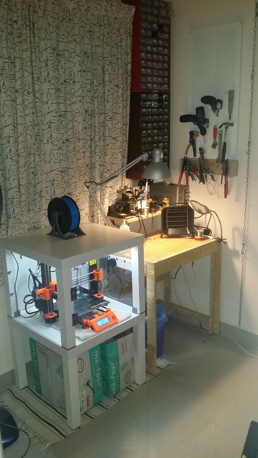
And Finally … The End Result
Here it is:
Future Upgrades
There are a few things I plan to upgrade for the enclosure:
- A magnetic door latch. I’ve ordered one on eBay, should arrive in a couple of weeks. I’ll make a door handle at the same time.
- Fit the LCD panel outside of the enclosure. The ribbon cables will likely need to be extended, I have ribbon cables and IDC connectors, so this should be straightforward.
- An extraction fan. I plan to fit a 120mm fan on the rear. Ideally this should vent to outside, maybe through a window. I’m thinking to fit an extraction fan to the room so maybe it just needs a hose to reach that.
- I noticed when I had the printer on my living room carpet, with the top part of the enclosure covering it, it was extremely quiet when printing. But when fully assembled and placed in my utility room, I could hear the Y-axis move from the next room. I think the thick-pile carpeting in my living room helped absorb the sound from the printer, so it might be worth experimenting with a small carpet under here (The thin mat pictured above doesn’t do much as far as absorbing the sound. I placed it underneath because I needed to slide the entire enclosure from my living room the the utility room at 2AM without making much noise. 😎)
- A UPS, to take care of brown outs and other minor power interruptions while printing.
- A software controlled power switch. It would be nice if I could control the power from the enclosure lighting and also the printer itself from the rasberry pi. I know how to do this in theory with relay boards, but given that it is switching live AC mains current, I should probably leave this off till I have more experience.
Originally created with EverNote at 20170211T095622Z
