3D-printed keycaps … and the possibility of backlit keys!
I’ve not been happy with the keycaps on my 737 FMC. I’ve tried a few methods of printing them:
- printing the letters recessed on black filament, and then using a fine tipped paintbrush, filling in the recessed parts with white acrylic paint. This method was ok for single letters, but for keys with multiple characters such as “EXEC”, my hand painting skills were not up to the task.
- Printing a blank keycap with white filament, and then printing the label on 2 layers of transparency sheets. This involves cutting the transparencies into perfect rectangles (the edges look ugly when viewed close up otherwise) and aligning them perfectly. Again, this method is let down by my handywork skills (which is why I prefer the precision of a computer).
While working on a different project over the weekend, I did some experiments. First I made some regular keycaps in tinkercad:
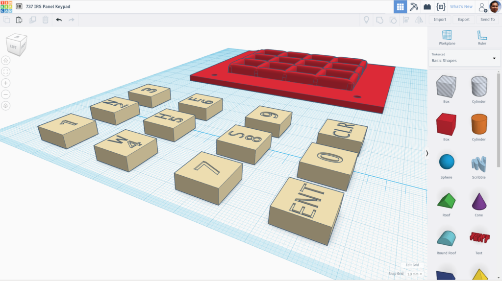
The blocks were 14mm x 14mm x 5.4mm. There’s a recess (not seen in the above picture) on the underside for the keycaps to fit the switch’s actuator. The letters are created as a “hole” and raised to 5mm height, and are > 4mm in thickness, and end up creating an embossed image into the block when grouped.
What i did differently was to print them using white filament up to 5mm, and then print the last two layers using black filament. Here are the results:
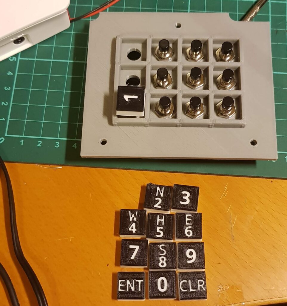
They look much neater than my hand made keycaps.
How to print different layers in different colours
To print different layers in different colors on my original prusa mk2 3D printer requires some trickery. First I exported the keycaps as a .STL out of tinkerCAD.
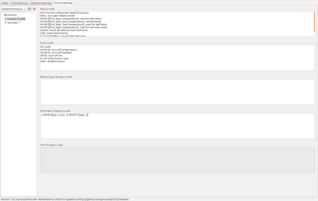
Next I opened Slic3r. The first time you need to make some changes to Slic3rs’s settings, under Printer Settings tab -> Custom G-Code:
Next I opened my exported STL from TinkerCAD into Slic3er. Instead of the usual “Send to Printer”, I used “Export G-Code” and wrote the G-Code out to a .gcode file.
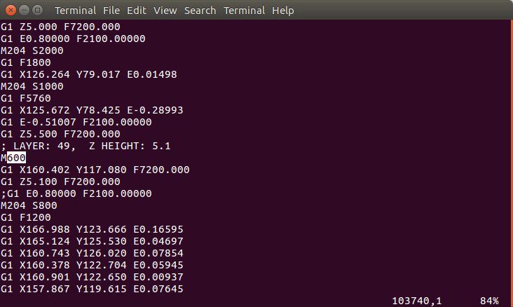
I opened the .gcode file in an editor, and searched for the comment line containing “Z HEIGHT: 5.1” (I printed this at 0.1mm layer height. If you’re using the default 0.2mm, you will need to look for “HEIGHT 5.2” instead). I inserted a blank-line with the word “M600” immediately after it. I also placed a semi-colon (commenting out a line) after it that begins with “G1 Exxxx”:
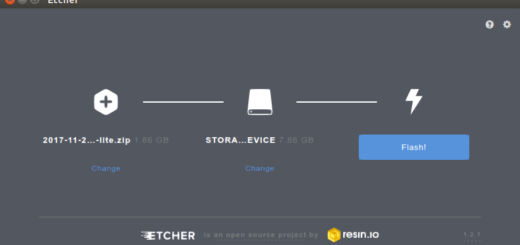
I then sent this .gcode to the 3D-printer, and started printing with white filament loaded.
Around the time it was printing Z-Layer 5.0 (you can monitor this from the LCD panel on the printer or from Octoprint’s G-Code Viewer tab), I waited by the printer. When it has done printing Z-Layer 5.0, the printer automatically paused the print and started beeping and displays a prompt to remove the existing filament.
At this point I changed to print using black filament. The remaining layers to be printed are for the material surrounding the embossed letters, thus creating a black face, and leaving the recessed letters in white.
A slight downside to this is that when the keycaps are viewed from the side, you can see the black and white layers. This may be ugly if the side of the keys are visible. It’s fixable by painting the sides by hand with black acrylic, something i can do easily as it doesn’t require much precision.
Backlit Keys!
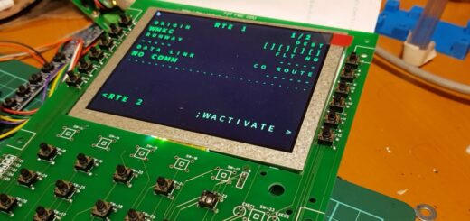
This opens up a few interesting possibilities. As an experiment, instead of using solid white for the base I used clear PLA, while retaining black PLA for the topmost layers. Here’s what they look with a LED underneath:
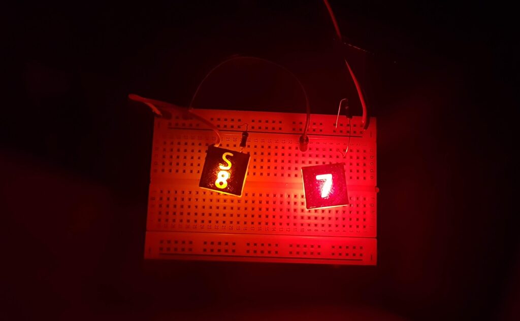
I think with some tweaking of the LED brightness and adding a few more layers of black, they may end up looking quite decent. Not as good as the ones made with a CNC machine, but when all you have is a 3D printer, this is probably acceptable.
It looks like at some point I will create a new version of my FMC PCB, but with support for backlit keys.
Originally created with EverNote at 20180702T104902Z