Adding End-Stops / Limit Switches to the 3018 “Woodpecker” CNC Router
In its original design, the 3018 “Woodpecker” CNC Router, a cheap entry-level unit found on eBay and AliExpress, will happily tell the stepper motors to keep moving along the axis, even if the work bed or spindle carrier is bumping against the end of its range of movement. This is because the router doesn’t actually have any absolute measurement of where it’s current position on the axis is. It assumes it is at the “home” position (machine coordinates 0,0) whenever it is powered on, and will allow any movement relative to that position.
This is not such a big deal with CNC machines as they are with 3D printers: CNC’s usually operate on material placed somewhere on the bed, so it is more important that operations are performed relative to the work piece rather than the work surface. Most jobs begin by manually positioning the bit on the bottom left corner of the work piece, rather than the work surface, and setting this as the “work” home position.
You’ve also probably heard the awful sound that happens when you’ve accidentally sent the bit beyond an axis, the stepper motor is trying to turn the lead screw, but the screw is not able to turn.
They way to prevent this from happening, and also to tell the router where “home” is, is to add what are called “end stop” switches to your CNC. These are mechanical switches that are placed strategically so that when the lead screw is reaching the end of its range, some moving part along the axis causes the switch to be closed.
The woodpecker controller that comes with the router already has support for end stops. If you look at the pins at the bottom:
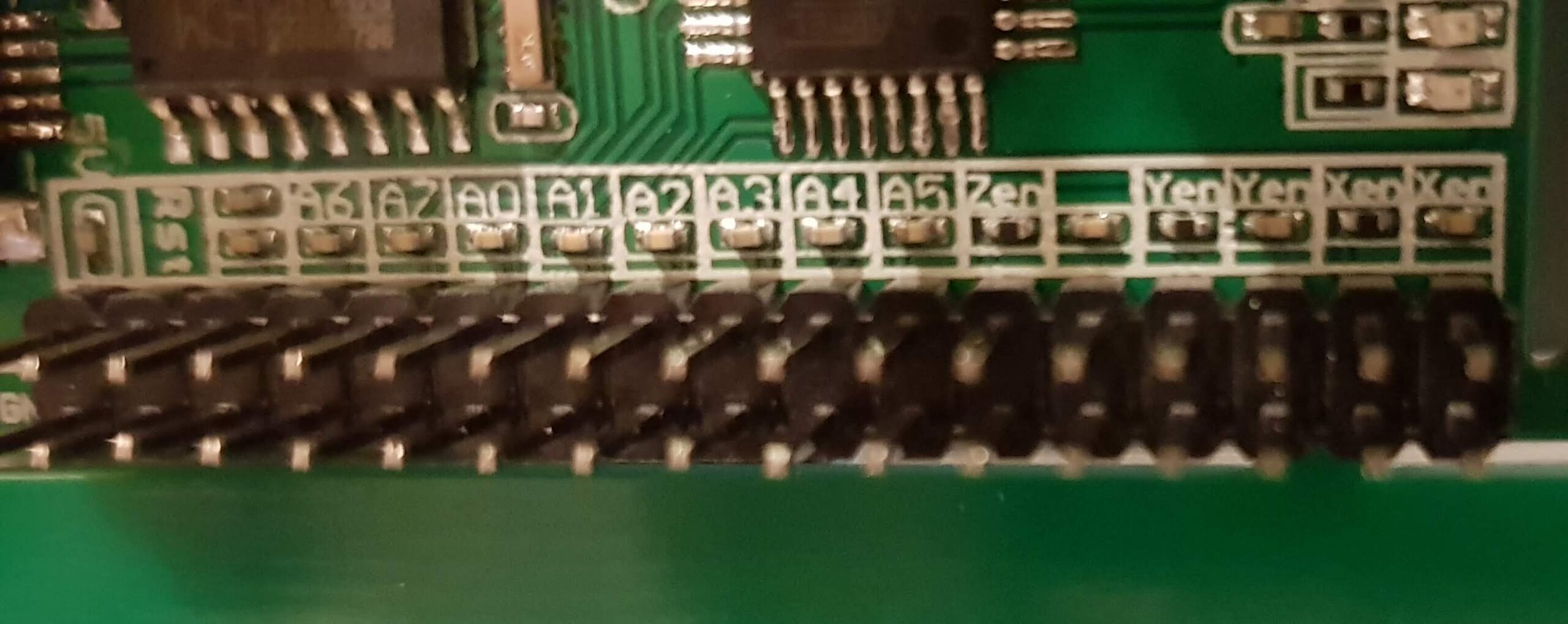
The last 6 pins are labelled “Zen”, “Yen”, and “Xen”. Those aren’t the surnames of the designers of the board, but rather they stand for “Z-Axis Enable”, “Y-Axis Enable”, and “X-Axis Enable”. Movement along that axis is only allowed when the two pins are “Not Connected”, as it is by default. So the job of the endstop switch is to close that circuit when the end of travel is reached.
End stop switches look like this:
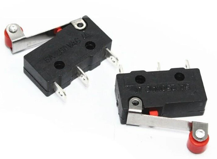
The lever, when pushed down closes a switch. There are three sets of pins. One pair is “normally open” and the other pair is “normally closed”. For each position where we wish to place and end-stop, we need to join the two wires on the Woodpecker header to the “Normally Open” pair of the end stop switch.
I bought a pack of 10 of these end stop switches on eBay (search for “KW12-3”) for a grand total of USD1.19 with free shipping.
To attach them to the printer, I designed some 3D-printed mounting brackets for the switches.
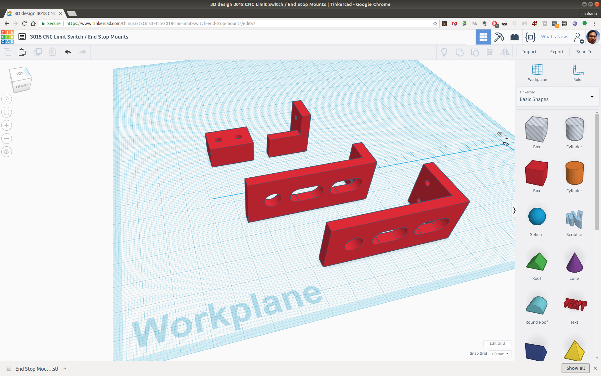
They can be found here: https://www.tinkercad.com/things/5txOc53Eftp-3018-cnc-limit-switch-end-stop-mounts
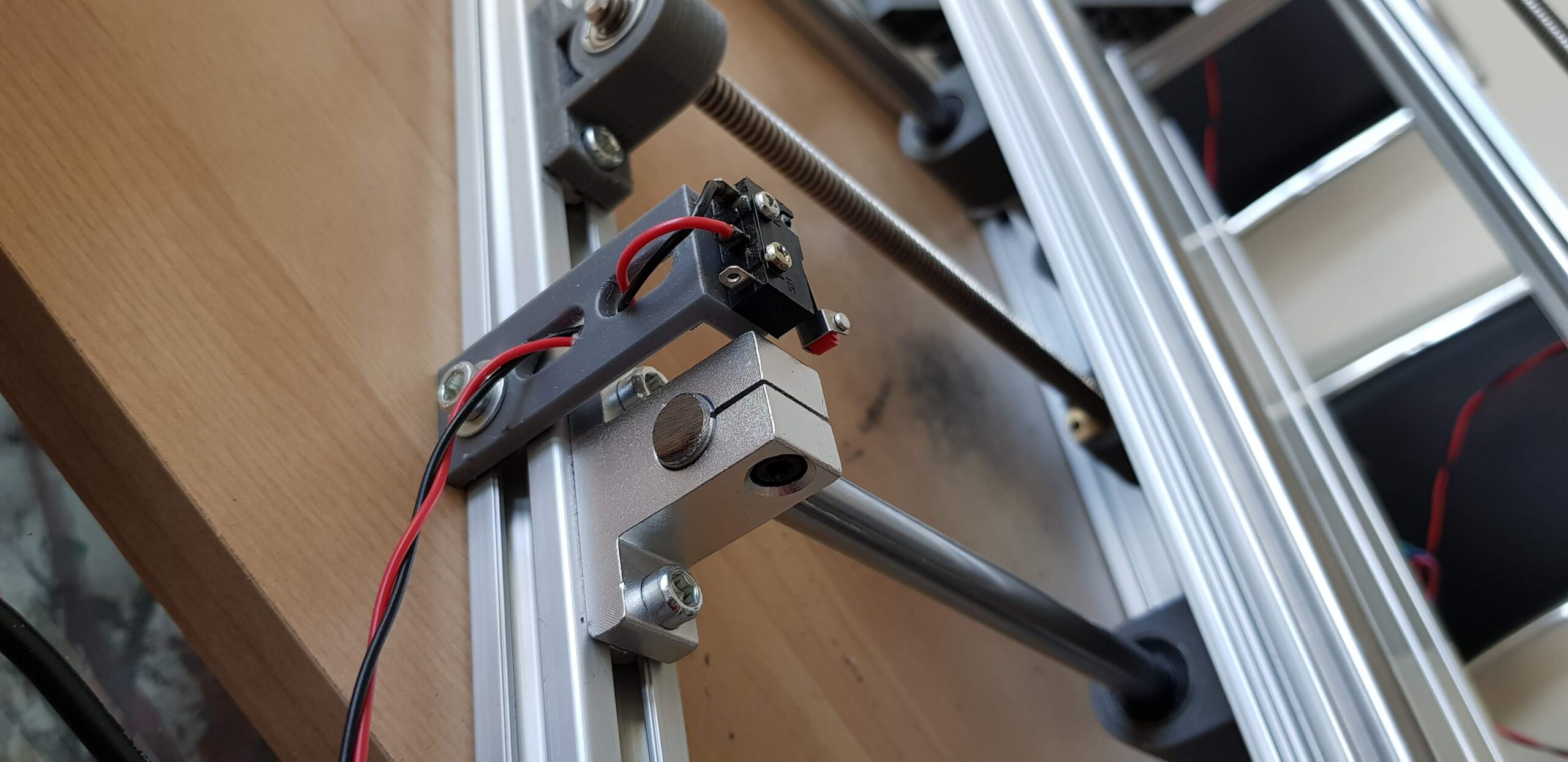
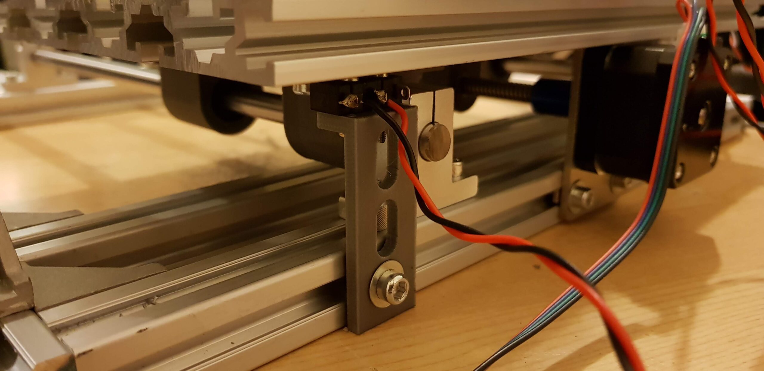
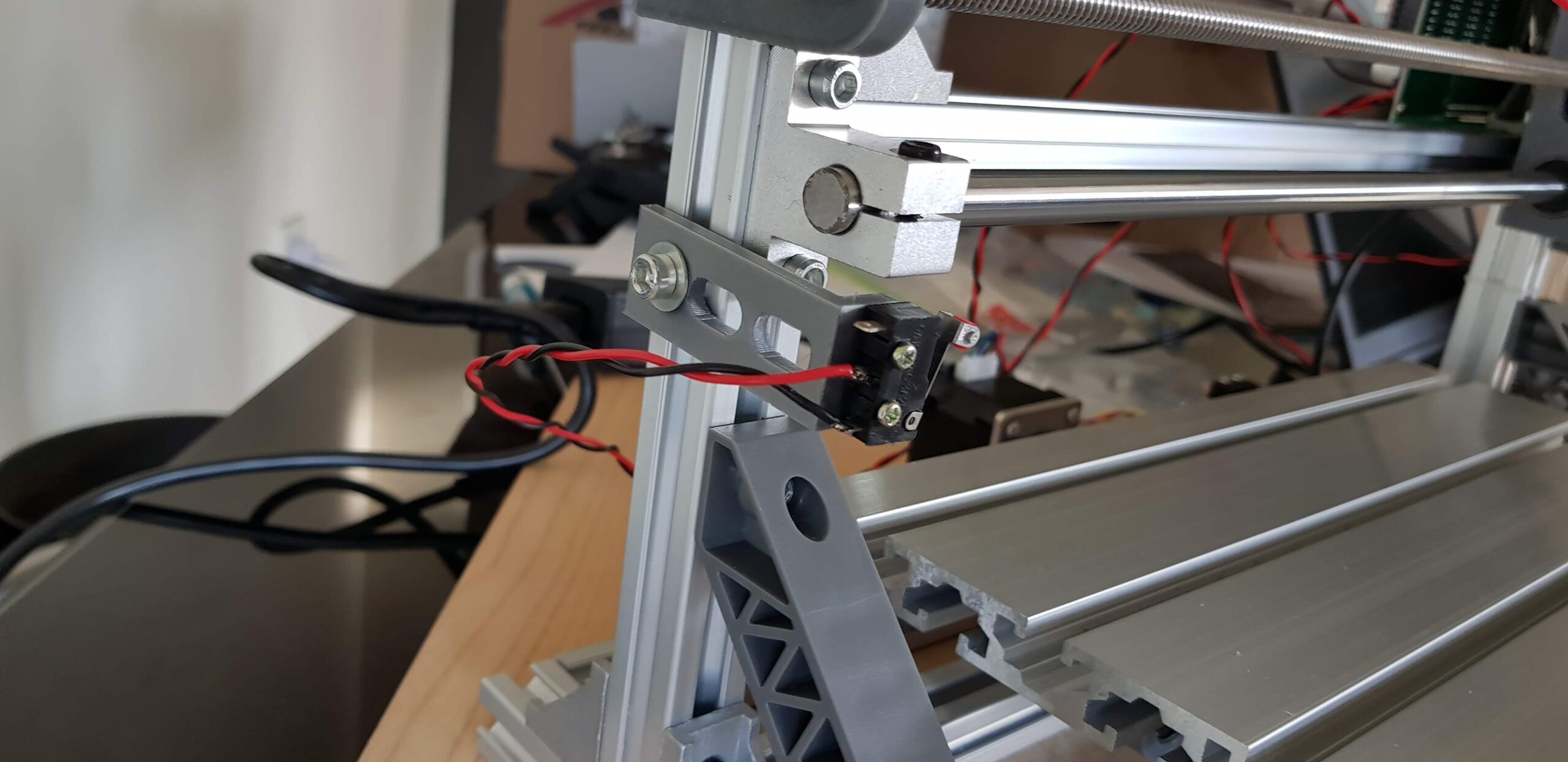
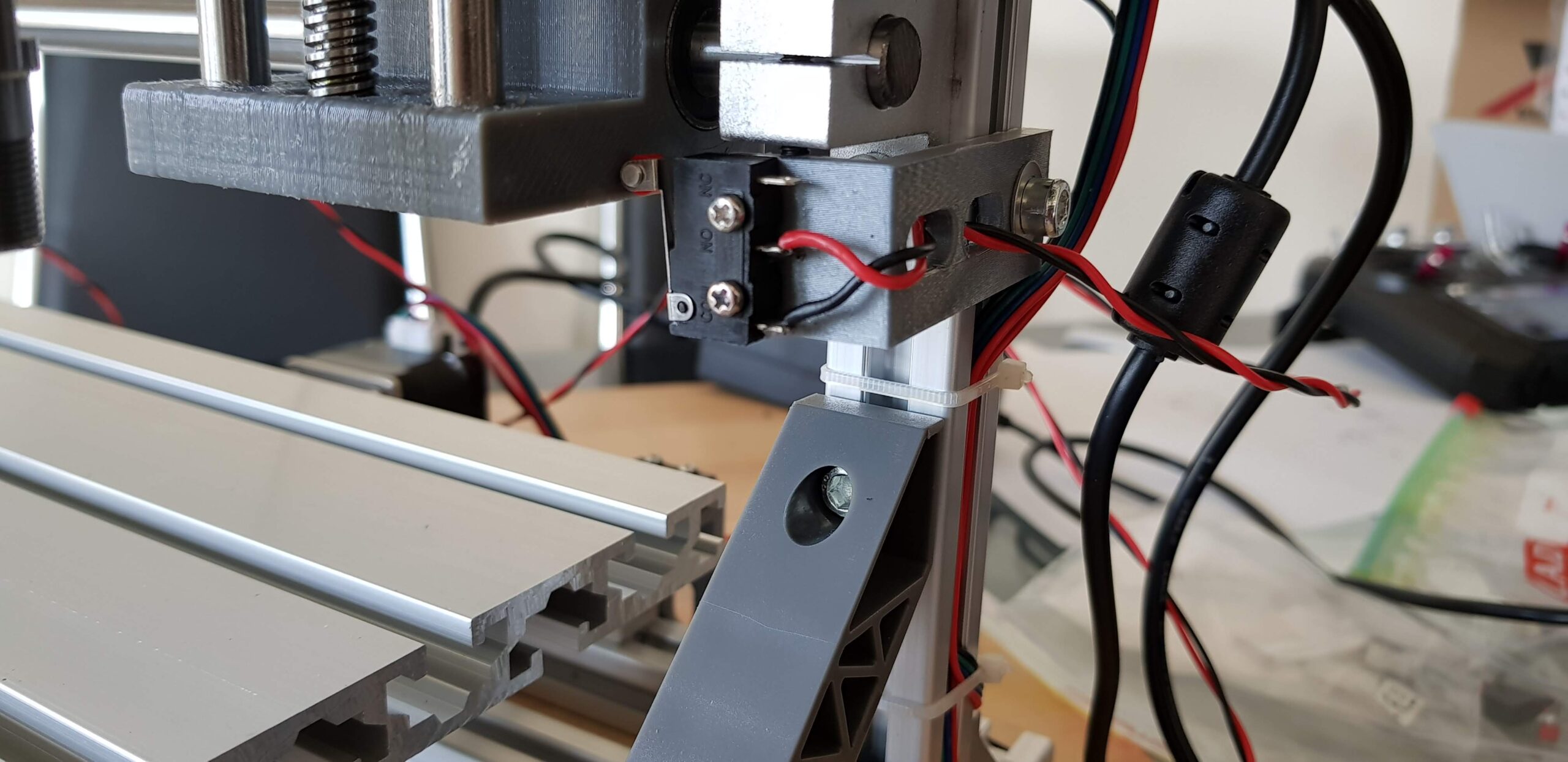
There a total of 5 — two each for the X and Y axis, and one for the Z. Here they are in place on the CNC Router:
Y Axis (Front)
Y-Axis (Rear)
X-Axis (Left)
X-Axis (Right)
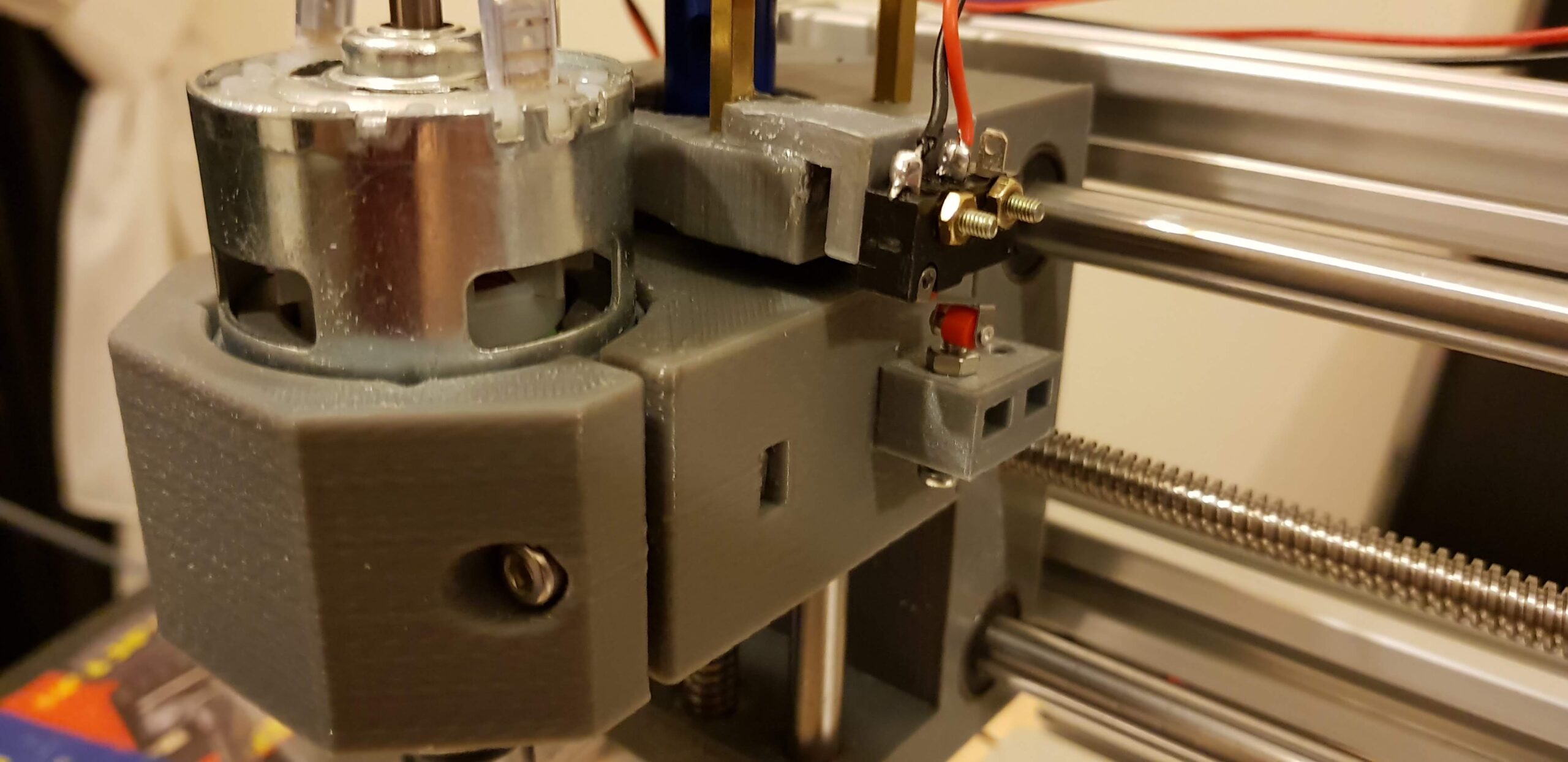
Z-Axis (Top)
For the Front, Rear and Left I was able to use the smaller of the brackets I designed. The Right side however, needs a slightly longer reach as the limit is further away, due to the motor coupler.
For the Top limit switch, there was nowhere to attach the mount. So I ended up designing a holder for the switch that was super-glued to the fixed part of the spindle module. I also made a block that is superglued to the moving part of the spindle module. This holds a m3x25 bolt, held in place with a captive square-nut and a regular nut for tightening. It is the bolt that presses against the limit switch, it is possible to adjust it’s height it until it only clicks towards the very end of the range of travel.
Note: For the superglue to work well on PLA, I applied a liberal amount of it, and also clamped the parts down and letting the glue set for a few hours.
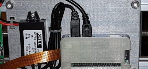
On the other end of the cable, I simply crimped them onto pins and inserted them into a 2-pin DuPont shroud. The woodpecker board already has pull-up resistors enabled and also capacitors to minimize the effects of noise, so these wires can connect directly to the appropriate header (X, Y, Z) on the woodpecker’s pins (You may also want to add additional buffering of the signals. I went without). It doesn’t matter which of the two pins of the axis you connect a limit switch to, they are considered the same to GRBL, and it knows which one is triggered because it knows which direction the head was moving in when the limit switch triggered.
Finally, secure all the wiring with cable wrap, so they don’t get in the way. Make sure the Top switch wire has enough slack so the spindle module can still move to the extremes the X-carriage.
GRBL Settings
The limit switches do not work immediately; you have to enable them first. To do this, I used the console panel inside cncjs.
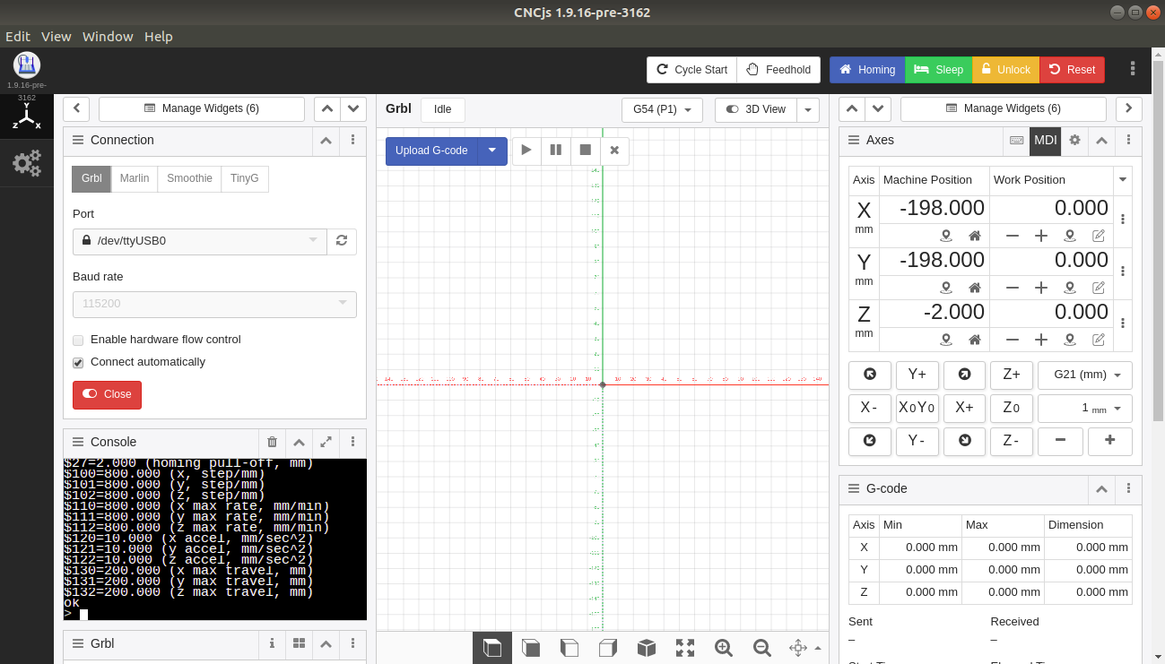
There are a number of GRBL (the firmware that runs in the woodpecker board) settings that apply. You can see the current settings when cncjs first connects to the woodpecker. To see the current settings at any other time, type “$$” followed by enter in the console panel.
Here are what my settings look like:
| > $$ $0=10 (step pulse, usec) $1=25 (step idle delay, msec) $2=0 (step port invert mask:00000000) $3=5 (dir port invert mask:00000101) $4=0 (step enable invert, bool) $5=0 (limit pins invert, bool) $6=0 (probe pin invert, bool) $10=3 (status report mask:00000011) $11=0.010 (junction deviation, mm) $12=0.002 (arc tolerance, mm) $13=0 (report inches, bool) $20=0 (soft limits, bool) $21=1 (hard limits, bool) $22=1 (homing cycle, bool) $23=3 (homing dir invert mask:00000011) $24=25.000 (homing feed, mm/min) $25=500.000 (homing seek, mm/min) $26=250 (homing debounce, msec) $27=2.000 (homing pull-off, mm) $100=800.000 (x, step/mm) $101=800.000 (y, step/mm) $102=800.000 (z, step/mm) $110=800.000 (x max rate, mm/min) $111=800.000 (y max rate, mm/min) $112=800.000 (z max rate, mm/min) $120=10.000 (x accel, mm/sec^2) $121=10.000 (y accel, mm/sec^2) $122=10.000 (z accel, mm/sec^2) $130=200.000 (x max travel, mm) $131=200.000 (y max travel, mm) $132=200.000 (z max travel, mm) |
To enable the limit switches, you have to set $21 to “1”. This is done by issuing the command:
$21=1
and pressing enter. The settings you make will remain set even if the CNC is switched off.
Once you have set this, the limit switches are monitored. If you now use the cursor in CNCjs to move the bit to one of the extremes, you will see the following in the console window when this happens:
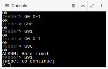
Once a limit switch is triggered, the spindle is automatically stopped and the woodpecker board goes into a locked state to prevent any damage from occuring. You will know this because the movement buttons will be greyed out. To resume using the CNC again, you need to do to things, (a) Reset and (b) Unlock. This can be done by sending Control-X followed by $X, or just press the coloured buttons on the top of the cncjs window.
On my machine, the first movement away from the limit switch position may trigger the cnc to become locked again, in which case I just need to Reset and Unlock it again.
This is a good time to check if your steppers are turning the right way … I look at my CNC with the gantry at the back, and I expect my axes to be laid out as follows:
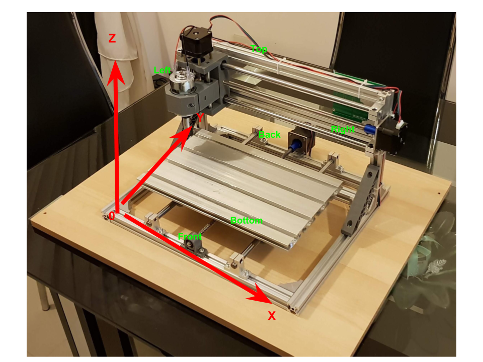
The front, top, left is considered the “Home” or “0,0,0” position for me, with the coordinates increasing in value as you move the bit right, back, and up (since 0 is at the “top”, you can’t move up, only down, so all the Z-level work is done in the negative range).
Not everybody agrees on this, so the cnc has options to change these assumptions.
If moving the spindle bit using the cursor controls in cncjs moves them in the “wrong” direction that you expect, you most likely have to invert that particular axis. This can be done using the $3 variable, using the following values:
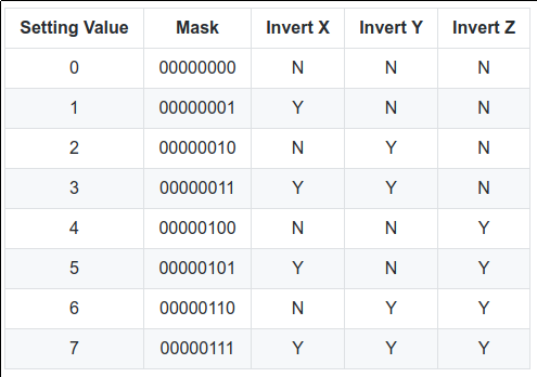
It is important that this is set correctly before you try to enable “Homing”, as everything will be messed up otherwise. On my CNC, I used a value of $3=5 (Invert Z and X) to get the axis laid out according to the photo above.
To enable Homing, set $22=1 (Homing cycle, enabled). Now when you send the $H command, or press the “Homing” button at the top of cncjs, the cnc should raise the bit, and seek to the home position.
If you find it is seeking in the wrong direction, you can tell it to invert an axis for homing, by setting the value of $23 (use the same table as $3 above). To get the Home in the top, Left, Front position, I needed to set $23=3 (Invert Z and X).
There is another setting, $27, homing “pull-off”. after detecting the home position, the cnc can move forward along the axis by a certain mm. This is to prevent the limit switches from triggering again with the next movement. On my cnc, I needed to set $27=2 (homing pull-off of 2mm).
With these set correctly, issuing $H or pressing the cncjs Homing button will cause the spindle head to move to the Home position, and set work coordinates to 0,0,0.
It should also set the machine coordinates to 0,0,0; however it’ doesn’t. Traditionally, CNC machines have their machine coordinates set to operate in “negative space”, and therefore Home is defined as the most negative position in the workspace (i.e. it assumes machine coordinates 0,0,0 is at the back, right, top). The CNCÂ can be changed to work in “positive space” by uncommenting the HOMING_FORCE_ORIGIN option in config.h when compiling the GRBL firmware. Unfortunately, the GRBL in my woodpecker board was set to work in “negative space” when it was compiled, so I am stuck with it until I figure out how to reflash the firmware in my woodpecker board.
To make things worse, it seems the woodpecker board has a generic firmware, and it thinks that my home is at -198.0, -198.0, -2, i.e. that my board is 200mm by 200mm (adjusted by 2mm of “Homing Pull-Off”). Hrmph. This means I need to go through a set of corrections if I want to know where exactly in machine coordinates a particular spot in my work surface is. The coordinates are still valid and usable, i.e. if I home and then tell the cnc to go to those machine coordinates, it will consistently go to the same place, it’s just that they’re offset by weird values.
For GRBL to know what the maximum negative space is, it needs to know the size of your workspace. These are defined in the following GRBL variables:
| $130=200.000 (x max travel, mm) $131=200.000 (y max travel, mm) $132=200.000 (z max travel, mm) |
So for my 3018 CNC router, I set these to:
|
$130=300.000
$131=180.000
$132=50.00
|
With these set, when I home CNC machine at the start of each usage, both the machine and work the coordinate systems becomes consistent and repeatable. In fact, once you enable homing, the first operation you always must do when first powering on the cnc machine is to home the system, as the GRBL will not accept any other operations until this is done.
Here it is in action:
Notes:
- The GRBL in the woodpecker board is version 0.9j.
- A list of all the settings and also the commands in GRBL 0.9, and detailed explanations of what they do, can be found here : https://github.com/grbl/grbl/wiki/Configuring-Grbl-v0.9.
- In the Axes panel, under machine position, there are buttons to zero-out and return to home for each axis. These don’t work on the woodpecker, as it uses commands from GRBL 1.1.Â
- Once home’d, you may find a gap between where the bit is and the corner of your work surface. If this is the X-axis, you can loosen the mounts below the work surface and slide the work surface to the left or right. If it is the Y-axis, you may need to adjust the mounting holes for the limit switch by editing the 3D-model of the mounting bracket, to make it trip closer or further away.
Originally created with EverNote at 20180807T200311Z