737 FMC CDU – Questions and Answers
It’s Mail Time! 😃
I received some questions regarding the 737 FMC CDU design I posted earlier. I’ve decided to answer them in a post as the questioner suggested, in case others have similar concerns.
* How can i get the PCB. Do you have for sale?
See my blog post here: https://blog.shahada.abubakar.net/?p=8210
* You use the 5″ display onscreen menu to control the display brightness. I wanted to use a potentiometer, any specific potentiometer you have in mind that can work with the PCB?
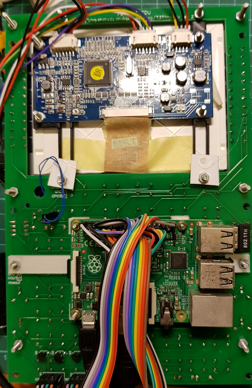
The display I used was from www.good-display.com. The link I bought from is broken, but this seems to be the current equivalent http://www.good-display.com/products_detail/productId=107.html. Make sure it has a 4:3 ratio, i.e. 640×480 It came with a controller board that supported VGA. I used a HDMI to VGA adapter and a male-male VGA adapter (in lieu of a vga cable) to connect the display to a Raspberry Pi. It’s not purely digital but the output is probably much better than using the composite video output of the Pi.
This 5″ Display I used only allows brightness to be controlled from the buttons on its own controller’s panel, which drive the on-screen display. So I don’t really have any other way to control brightness other than to use that — which in reality means it’s been set once and left as is, as I don’t really have access to the display controller’s keypad (I just attached it under the LCD).
I left a hole on the PCB where the brightness control knob goes, with two screw holes. My thoughts at the time was that someone could mount whatever controller they needed for the knob (a potentiometer, or a rotary encoder) on a plate below the PCB, mounted via the two screw holes.
If your display supports a potentiometer for brightness control you could potentially (😃) use this hole in the PCB and attach it there. It would be wired directly to your display and so other than being physically mounted on the PCB, wouldn’t actually depend on anything in the PCB. So the choice and type of potentiometer would depend totally on what works with your display.
The second idea I had which (I’ve not explored yet) was to use a rotary encoder (something like this https://goo.gl/XGZNcG). This would send digital pulses on two lines to indicate if it was being turned clockwise or counter clockwise. These could be read by the microcontroller by connecting it to two GPIO lines, and perhaps a change in brightness simulated by playing with the colour palette. It won’t do much for the LCD backlight, but at least turning the knob would have some effect. To support this there are three pins near the hole for the brightness knob labelled P4, which are GND, GPIO-A and GPIO-B. These are connected to the similarly named pins on the LED connector — it’s just a direct connection with no electronics in between, so you could also use them for any other purpose that suits you. I brought them to the LED connector just to make wiring to the controller easier.
* I was thinking if it’s not possible to connect the 5″ display directly to the raspberry pi/ Arduino using its flex connector instead of VGA/HDMI? I know the power cable needs to be plugged somewhere into the raspberry pi or arduino to juice up the display. Just a curious thought
The port on the Raspberry Pi is a Display Serial Interface (DSI) … I really don’t know much about it. There is a Raspberry Pi Branded 7″ touch screen that uses it (https://www.element14.com/community/docs/DOC-78156/l/raspberry-pi-7-touchscreen-display); even this needed a special board to “to power the display and convert the parallel signals from the display to the serial (DSI) port on the Raspberry Pi“. So finding a display of the right size and ratio that works directly with the DSI port might be a challenge.
* did you use Raspeberry Pi or Arduino? Can you please send me the codes you use to run them? (I know you showed a link to the code but I don’t quite get it.
The PCB is designed to be independent of the controller … i.e. other than the hole, there isn’t anything related to the display on the PCB. The keyswitches are organized in a keypad-matrix layout, so any controller than can process rows and cols as keypad should work with it. The LEDs are also designed to be driven by low power GPIOs.
So in theory you could use any controller you like, e.g. arduino or Pi. Someone mentioned a PoKeys USB adapter to me once too (I have no experience on this, but from what I’ve read of the manual I believe it might work). You could just use an arduino or PoKeys just to adapt the keypad and drive the LEDs, and connect the display to a VGA on your X-Plane PC and pop out the FMC and drag it to the FMC’s LCD.
I went with the Raspberry Pi because it has the advantage of being able to have its own display output, so a single Pi can drive the display, handle the keypad, and also the LEDs, and interface with X-Plane over the network via Ethernet. Going over the network works better for me as I have two X-Plane PCs, one on Linux and one on Windows, so it’s easier to switch over as compared to physically having to move a USB cable across.
You’re the 3rd person this week who’s reported not being able to access my source code. — I think I messed up something in the firewall a week or two back. Let me see if I can fix that over the weekend. Else I can send you a zip of the current source. I should probably check that the current source actually works first though.
Actually, if you’re planning to use a Pi what I might do is set up a repository so you can just “apt-get” and install a package … this might help others too, especially if they’re not familiar with compiling source code on Linux. It would also be easier for me to fix bugs and push updates out. Just something I’ve been thinking about. This would probably need a few weeks.
[Update: See this post on how to install the Pi software https://blog.shahada.abubakar.net/?p=8326]
* You mentioned that if using REV 2.0 of the PCB board, the cathode OR symbolically “(-)” line should be on the right? I currently see you have the diodes (-) on left when when viewing from switches side (front of PCB) board. Is it all diodes D1-D9 are affected by this error or just some specific ones?(I see all are facing leftward direction)
They should all be affected by the error. Let me see if I can take the faceplate off mine and post a photo of what I ended up soldering … here you go!

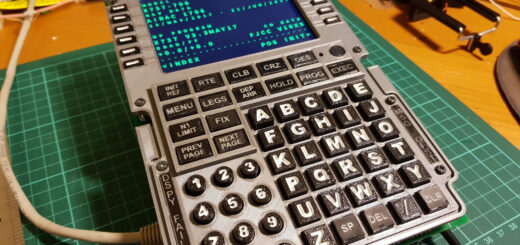
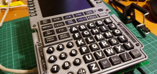
front
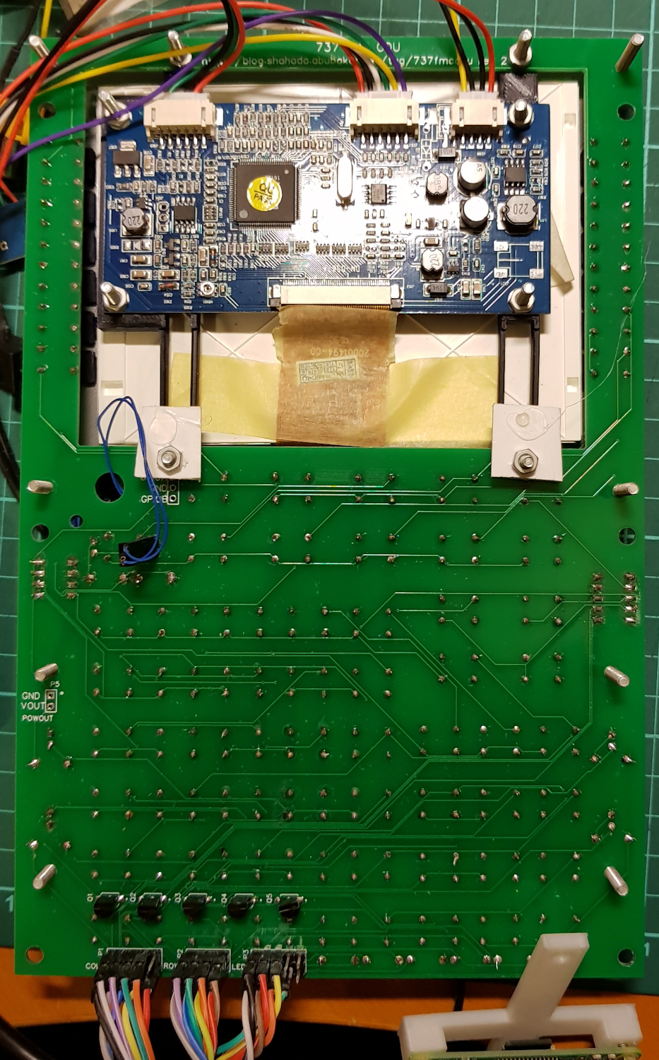
Rear
Rear with Pi Mounted
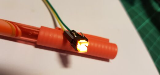
* you also mention that the LED for “ofst” is wired backward and that the cathode/longer leg should be toward the bottom of board. I believe that the longer leg is always anode and NOT CATHODE
* You also said that “for all other LEDs, the cathode/longer leg is toward the top of the board…I believe that there is no change to the other LEDs and they are good except for the “ofst LED” that needs to be soldered backward? Am I right?
You are probably right on the cathode vs anode vs long vs short. My electronics skills are more at the if-it-doesn’t-work-this-way-turn-it-the-other-way-around level when it comes to LEDs. If you look at the logical schematic at https://goo.gl/myzxWM you’ll see that all the LEDs point the same direction except for OFST one which I had wired backwards in the schematic by mistake. When I laid out the PCB I got them all pointing the same way; but in reality the OFST LED’s connections are backwards, so to make it work the LED needs to be soldered on in reverse.
Note: These bugs affect the 2.0 revision of the board. The 2.1 revision should have the correct markings.
* where and how did you get the FMC plates with switches? Online or DIY too?
The faceplate was 3D printed from a design off Thingiverse. The details are on an earlier post (or just click on the “737 fmc” in the Categories on the Left and scroll down (so you can skip over my other unrelated posts). The keybuttons are from the same Thingiverse post too I think.
The designer who did the faceplate design has a link to the switches (and display) on the thingiverse page, if you’re in Europe these may be faster to source from. I found a similar one on eBay which was cheaper for me (search for “100Pcs Square Head 6x6x7.3 mm Tact Tactile Push Button Momentary PCB Switch”; here’s a link that works currently). The holes on the PCB are designed for the eBay one, but from the design schematics I believe they’re the same.
Overall I’m not too happy with these switches as the actuator is thin and tall … it’s meant to fit into a corresponding hole at the bottom of the buttons. But I found it quite hard to print the buttons with the holes perfectly. It could just be that I’m printing them wrong, but In the end I removed the holes and left the bottom of the buttons flat. They still press against the actuator just fine once you level the faceplate against the PCB properly, but because the actuator is thin and tall the button presses feel slightly wobbly.
I’ll revisit this at some point with a different design of switches that have a built-in LED so the keys can light up … that will need a new PCB layout. I’ve promised myself to actually complete the other projects (overhead panel, throttle quadrant) before starting on an upgrade of anything though … 😎
* What size Current Limiting Resistors Should I Use?
Resistors R1 – R5 are current limiting resistors for the GPIO signal feeding into the transistors. I used 1KΩ resistors. This should be fine for 3.3V GPIO (Raspberry Pi) and also 5V GPIO (Arduino).
Resistors R6-R9 are current limiting resistors for the LEDs. I used 330Ω resistors — but this depends on the voltage input (VIN) you supply to power the LEDs (the keypad side of it doesn’t use this voltage input, so it is purely to drive the LEDs) and also on your LEDs. 330ohm is the lazy-person’s-choice of resistor for use with LEDs, and is safe if you supply VIN from the Raspberry PI’s 5V output pin. If you want them slightly brighter, do calculate the appropriate limits based on your LEDs specifications and the VIN you supply.
Originally created with EverNote at 20171124T155826Z