737 FMC CDU – Interfacing X-Plane to a Raspberry Pi
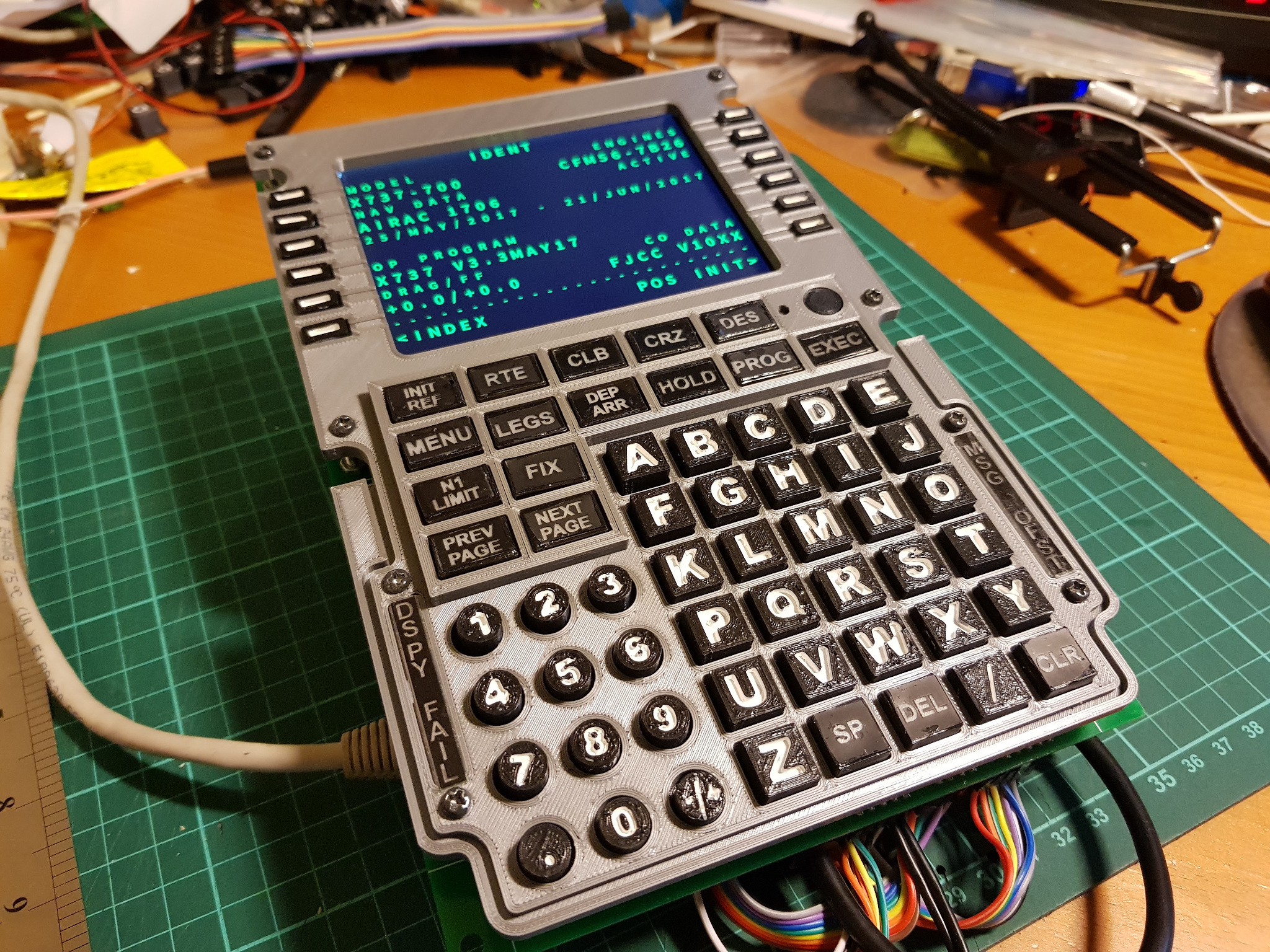
To connect the 737 FMC CDU PCB board to my X-Plane flight simulator, I used a Raspberry Pi 2. Almost any Pi model will do, provided it has the full 40-pin GPIO connector (i.e. not the early model A and B), networking, and video output to connect to the 5″ display.
The Pi talks to the FMC CDU PCB I made earlier using GPIOs. I needed 9 (cols) + 8 (rows) + 5 (LEDs) GPIOs which came up to a total of 22. Many of the GPIO pins on the Raspberry Pi serve dual-purposes, and so you must make sure to:
- not enable SPI
- not enable I2C
- not enable TTL Serial Port
- not enable PWM
A freshly installed Raspbian usually comes with these features disabled.
For ease of wiring I bought a Female-Female Jumper Cable strip and just tore out how many wires I needed.
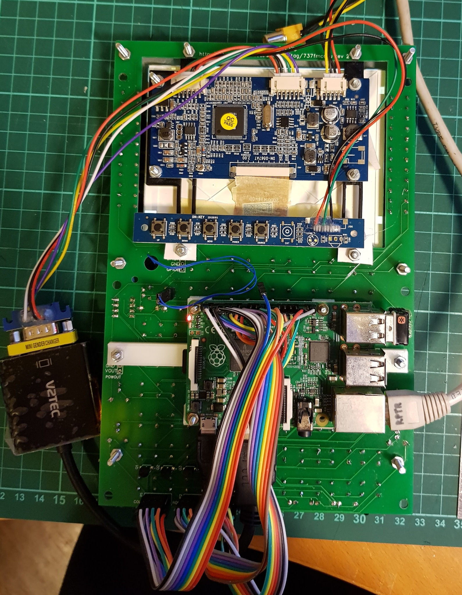
I also printed a bracket so I could mount the Raspberry Pi on the underside of the FMC CDU PCB using the existing bolts.
The first cable connects to “P1 – Cols” and was wired as follows:
|
Colour
|
P1 – Cols
|
Raspberry Pi (physical/wiringPi/BCM)
|
|
Black
|
1
|
8 15 14
|
|
White
|
2
|
10 16 15
|
|
Gray
|
3
|
12 1 18
|
|
Purple
|
4
|
16 4 23
|
|
Blue
|
5
|
18 5 24
|
|
Green
|
6
|
22 6 25
|
|
Yellow
|
7
|
24 10 8
|
|
Orange
|
8
|
26 11 7
|
|
Red
|
9
|
36 27 16
|
|
Not connected
|
10
|
n/a
|
The second cable is connected to “P2 – Rows” is wired as below:
|
Colour
|
P2 – Rows
|
Raspberry Pi (physical/wiringPi/BCM)
|
|
Gray
|
1
|
40 29 21
|
|
Purple
|
2
|
3 8 2
|
|
Blue
|
3
|
5 9 3
|
|
Green
|
4
|
7 7 4
|
|
Yellow
|
5
|
11 0 17
|
|
Orange
|
6
|
13 2 27
|
|
Red
|
7
|
15 3 22
|
|
Brown
|
8
|
19 12 10
|
The third cable is for the “P3 – LEDs” and is wired as below:
|
Colour
|
P3 – LEDs
|
Raspberry Pi (physical/wiringPi/BCM)
|
|
White
|
1 (VIN)
|
4 (5V)
|
|
Black
|
2 (GND)
|
6 (GND)
|
|
Brown
|
3 (EXEC)
|
21 13 9
|
|
Red
|
4 (MSG)
|
23 14 11
|
|
Orange
|
5 (DSPY)
|
29 21 5
|
|
Yellow
|
6 (OFST)
|
31 22 6
|
|
Green
|
N7 (FAIL)
|
33 23 13
|
|
N/A
|
8 (GPIOA)
|
N/A
|
|
N/A
|
9 (GPIOB)
|
N/A
|
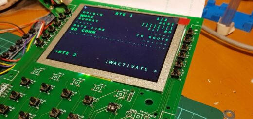
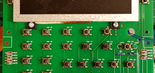
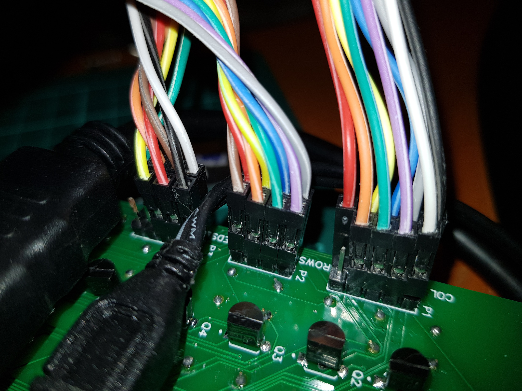
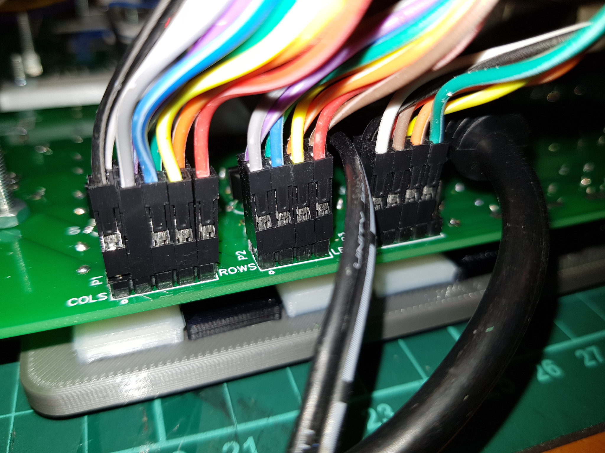
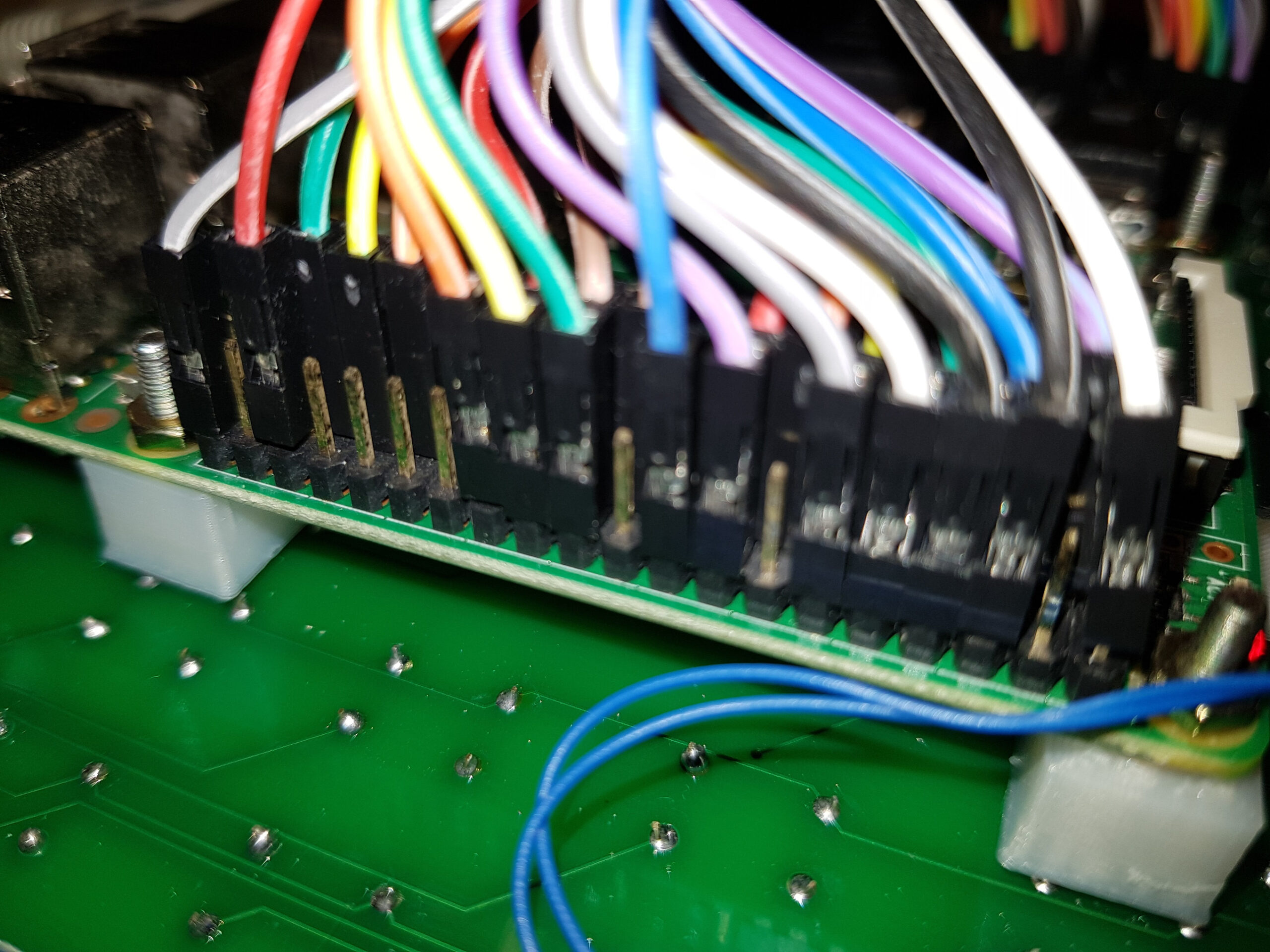
Here are some photos of the wiring connections on the FMC CDU end:
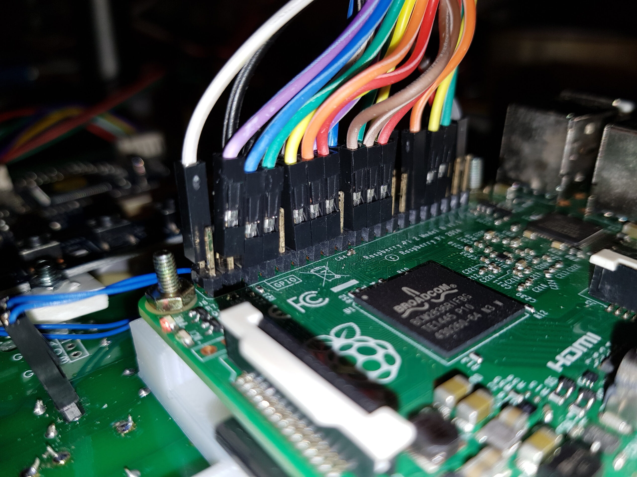
And this is on the Pi’s GPIO connector end:
Update
I’ve done some work on the software to interface the display and also keypad to X-Plane.
- Source code is at to https://github.com/dotsha747/Pi-XPlane-FMC-CDU
- There’s now a repository with prepackage binaries to make installation easier. Instructions on setting up a Pi can be found here: https://blog.shahada.abubakar.net/?p=8326
- There’s a FAQ here https://blog.shahada.abubakar.net/?p=8211
Originally created with EverNote at 20170602T112050Z