737 FMC CDU – PCB Board
Overview
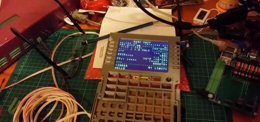
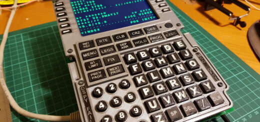
This is the PCB I designed to be used with the FMC CDU 3D Panel by “User0180″ on thingiverse. It has a cutout to suit the recommended 5” 4:3 LCD Display and features the standard 69 switches, as well 3mm LED positions for the EXEC, CALL, FAIL, MSG and OFST indicators.
It was designed to be hooked up to any microcontroller or I/O board that supports decoding a 9×8 matrix keyboard. The board also has transistors and current limiting resistors for the LEDs, allowing you to drive them from low-current low-voltage GPIO pins such as from the Raspberry Pi.
I used EasyEDA.com to design the schematic and PCB using their online editor. The design can be downloaded from the links, or you can get EasyEDA to fabricate the boards and ship them to you. The fabrication cost me USD20.19 for 5 pieces, and tracked shipping was an additional USD17.00 that took around 10 days.
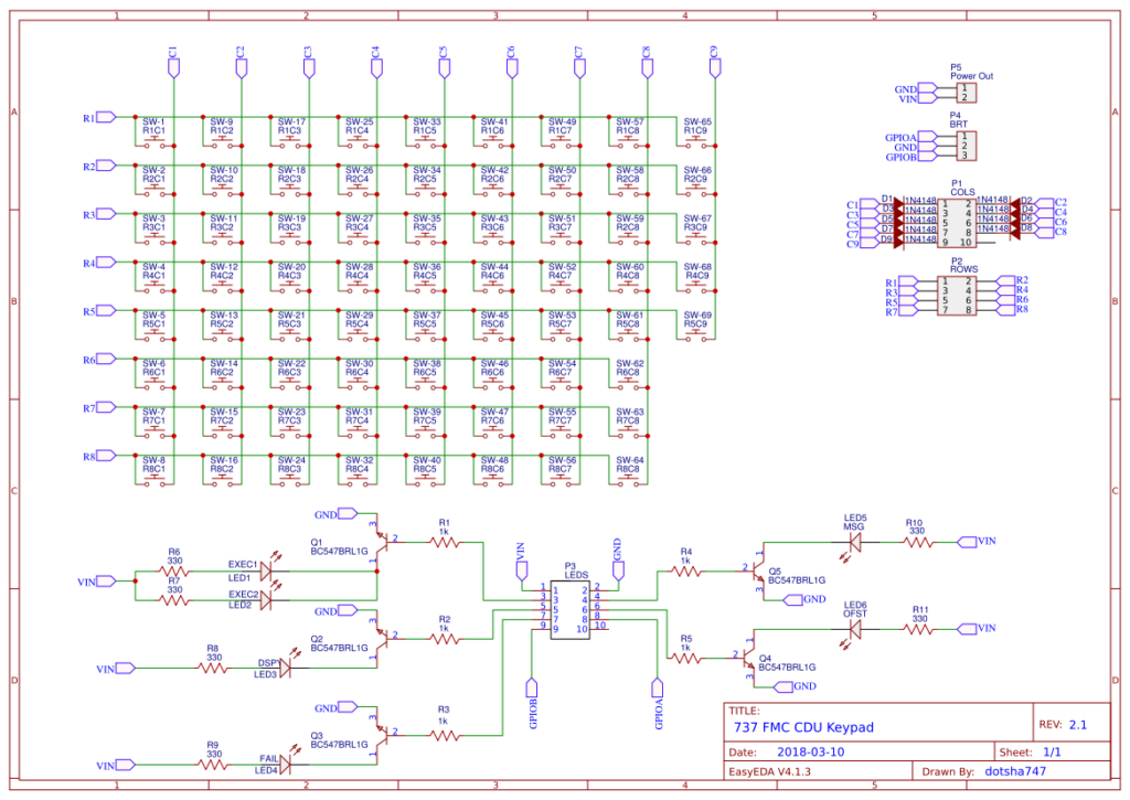
Schematic Design
I based my keypad schematic on the excellent article “How To Make a Keyboard – The Matrix“. To cover 69 keys I created a matrix of 8 rows x 9 columns (there are some unused key positions). The article mentions that to be able to handle multiple simultaneous keypresses, you need a diode on each keyswitch. However, with the FMC CDU, only one key needs to be pressed at any time, and therefore I only placed diodes only on the columns — there is much less to solder this way.
For the LED indicators, I did not power them directly from the input signals. Some microcontrollers such as the Raspberry Pi only have 3.3V outputs and very limited current to drive the LEDs. To overcome this limitation I used the GPIO only as a signal to turn on a circuit using a transistor for each LED. Each LED also has a current limiting resistor next to it — the size of this resistor depends on the voltage you supply and also the LEDs you use.
I made a number of connectors to hook the PCB up to the microcontroller. “P1 – Cols” and “P2 – Rows” connect to the columns and rows on the matrix keypad. Another connector “P3 – LEDs” provide input voltage and ground, as well as GPIO signals to control the LEDs.
The FMC CDU has a brightness knob to control the brightness of the display. My 5″ display however uses on-screen menus to set the brightness. I’ve brought out two additinal pins on the LED connector (labelled GPIOA and GPIOB) close to the brightness knob location. You may want to connect this to a potentiometer or a rotary encoder. In my case, I just used a dummy knob.
Here’s a screenshot of my schematic here for a more detailed view).
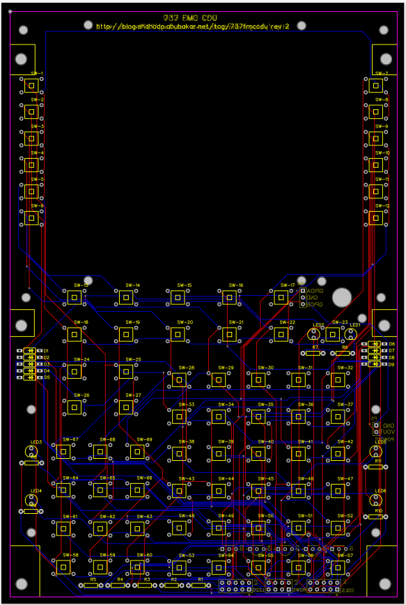
PCB Design
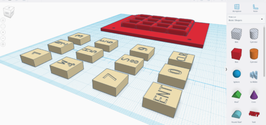
As I was designing the PCB to fit an existing physical model, I started with tracing the design of the FMC CDU Panel. I was not able to import the 3D model into EasyEDA’s PCB editor, so what I did instead was to import the .STL file into TinkerCAD. By applying TinkerCAD’s ruler, and setting the distance of the top left of the model to 0, I was able to accurately get the size of the panel and also the center position of each of the keys. I then used this as offsets in EasyEDA’s PCB Editor when positioning the PCB outline, LCD panel cutout, and also the position of each keyswitch.
The keyswitches used are similar to the ones recommended by User0180, but I found similar ones cheaper on ebay.com (search for “100Pcs Square Head 6x6x7.3 mm Tact Tactile Push Button Momentary PCB Switch”) at USD7.45 for 100 pieces with free shipping, which arrived within two weeks. I needed the keyswitch component to have its origin at its center, so ended up designing my own component for this, with the holes for the feet 200 mils by 300 mils apart. This way, when I keyed in the X and Y coordinate of the keyswitch in the PCB editor, it would fall centered exactly at that point.
The 3D Design for the FMC CDU faceplate did not incorporate any holes for lighting up the EXEC button. I placed two LEDs near the switch so that they could be positioned either above the key (as in the original  737 — this would require adding a slit to the 3D design) or as part of some sort of backlight for the EXEC key itself.
I placed the header connectors and transistors on the bottom side of the PCB — these would stick out and may interfere with the faceplate if placed on the top side. Finally I added mounting holes for brakets for the the 5″ LCD display and also for the brightness knob, should it be needed.
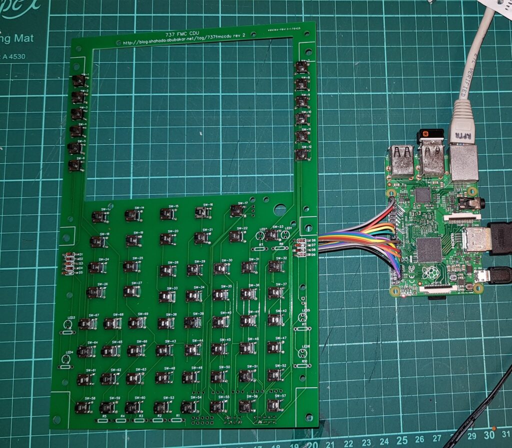
Here’s the PCB layout (click here for a more detailed view):
You should be able to connect the 737 FMC CDU PCB Board to any microcontroller such as a Raspberry PI, Arduino or I/O board, provided you have enough GPIO pins.
The P1 – Cols connector connects to all the columns in the matrix.
The P2 – Cols connect to the rows.
The P3 – LEDS connector has the following pins:
|
Pin
|
Name
|
Notes
|
|
1
|
VIN
|
Voltage Input. This voltage input is to drive the LEDs. You can feed any reasonable voltage you like in here, provided you size your current limiting resistors accordingly. This does not feed back into the GPIO signals.
|
|
2
|
GND
|
Voltage GND. If you are using a different power supply to feed VIN (for the LEDs) than what you use for your microcontroller, you will want to tie the grounds of the two supplies together.
|
|
3
|
EXEC
|
Connect this to your GPIO for the EXEC indicator. It feeds the activation signal into the transistors to switch on the LEDs.
|
|
4
|
DSPY
|
Connect this to your GPIO for the DSPY indicator. It feeds the activation signal into the transistors to switch on the LED.
|
|
5
|
MSG
|
Connect this to your GPIO for the MSG indicator. It feeds the activation signal into the transistors to switch on the LED.
|
|
6
|
OFST
|
Connect this to your GPIO for the OFST indicator. It feeds the activation signal into the transistors to switch on the LED.
|
|
7
|
FAIL
|
Connect this to your GPIO for the FAIL indicator. It feeds the activation signal into the transistors to switch on the LED.
|
|
9 and 10
|
GPIOA & GPIOB
|
This lead to a connector near the brightness knob. Â
|
Bugs
- If you are using the Rev.2 board, and following the matrix design in Komar’s blog post above, I discovered I’d got the diodes labelled backwards … so you will want to solder them with the Cathode/black line towards the right.
- If you are using the Rev.2 board, the LED for “OFST” is wired backwards … just solder on your LED with the cathode/longer leg towards the bottom of the board for this particular LED. For all other LEDs, the cathode/longer leg is towards the top of the board.
- These have been fixed on the Rev 2.1 board.
Downloading
The latest schematic and PCB design for the FMC CDU can be found here: https://easyeda.com/dotsha747/737FMCCDU_V2-83f14eb14ced4e928df00539a30b3de3 It is licensed under the Creative Commons CC-BY-NC-SA license.
If you want to order a PCB, see my blog post here: https://blog.shahada.abubakar.net/?p=8210
More notes on my 737FMC build can be found here: https://blog.shahada.abubakar.net/?cat=211
Where to Buy Stuff
To help everyone source the needed components, here’s a shopping list and some links on where to get the items from (as of 9 Mar 2019). I’ve assumed you’re planning to hook this up to a Raspberry Pi to use with X-Plane.
- The 737 FMC CDU PCB
- Note: If you’re buying the PCB from JLCPCB, you can combine shipping with parts from lcsc.com.
- 4:3 640×480 LCD Display with VGA input
- www.good-display.com 5.0” digital TFT LCD Module/LED Backlight/VIDEO VGA input Item# GDN-D567AT-GTI050NA-08C (what I used)
- ebay.com ZJ050NA + VGA Adapter Board (should be ok — let me know!)
- HDMI to VGA Adapater
- DB-15 Gender Changer Male-Male (so you don’t need a VGA cable)
- Raspberry Pi (2/3/Zero W/Zero WH)
- 69-pieces momentary key switches
- 9 pieces through-hole 1N4148 Signalling diodes
- 6 pieces 1/4W 330R through-hole Resistors (Current Limiting for LEDs)
- 5 pieces 1/4W 1K through-hole Resistors (Current Limiting for Transistors)
- ebay.com (multipack) (same as above)
- 5 pieces BC547 NPN through-hole Transistors
- 1-piece 40-pin 2.54mm pitch straight Male Header Pins
- 40-pin Dupont Female-to-Female Jumper Cables
- 3mm LEDs
- 3D printed Faceplate + Keys
Originally created with EverNote at 20170515T112700Z