DIY Dual Concentric Rotary Encoders with Push Button
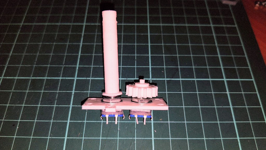
This is my fully 3D printed design for a Dual Concentric Rotary Encoder with Push Button. It’s useful for making the knobs for flight-sim radio panels, where there is an outer knob to set the smaller digits, and an inner knob to set the larger digits.
It’s inspired by a design I found on Youtube, where the designer, Theo Deckers, CNC’d a bracket to hold two regular rotary encoders together. I don’t have access to a CNC machine or the parts that Theo uses, so I decided to design one purely using 3D-Printed plastic.
You can buy a ready made part, but they are either expensive or have a large minimum order quantity (MOQ).
This design makes use of common cheap rotary encoders. Rotary encoders allow you to rotate the shaft infinitely clockwise or anticlockwise. For each click, it will report the direction the shaft was rotated in. Most also feature a push-button switch, where pressing down on the shaft closes a switch.
You can buy these rotary encoders in most electronics parts shops, or on eBay (search for “Rotary Encoder Push Button 12mm D-Shaft”. Here’s a link that’s valid right now, USD4.17 for a pack of 10 with free shipping). You’ll need two for each part.
Printing The Components
The components of the part can be donwloaded from my TinkerCAD project page at https://www.tinkercad.com/things/dwthDbal5YY.
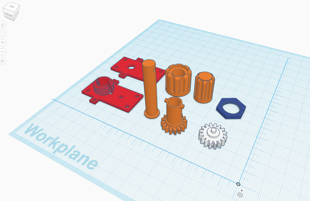
There are a number of components that need to be printed:
- Outer Knob
- Inner Knob
- Outer Shaft
- Inner Shaft
- Outer Encoder Cog
- Upper Plate
- Lower Plate
- Mounting Nut
I printed my parts on a Prusa Mk2 at 0.2mm layer height and 20% infill, with the exception of the mounting nut which I printed at 0.05mm layer height and 100% infill.
Assembly
You will also need the following items:
- 4pcs M3x24 bolts, or longer
- 12pcs M3 nuts
- a M3x12 bot
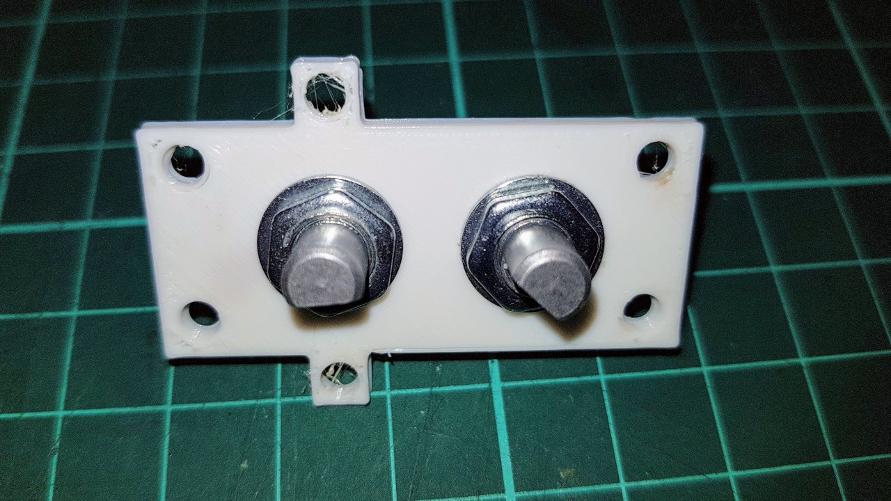
Start by attaching the rotary encoders to the lower plate.
Then attach the inner shaft and the Outer Encoder Cog to the D-shafts.
Next attach the four M3 bolts to the upper plate. Secure them tightly with four M3 bolts. Thread another four bolts till they are roughly 7mm from the upper plate.
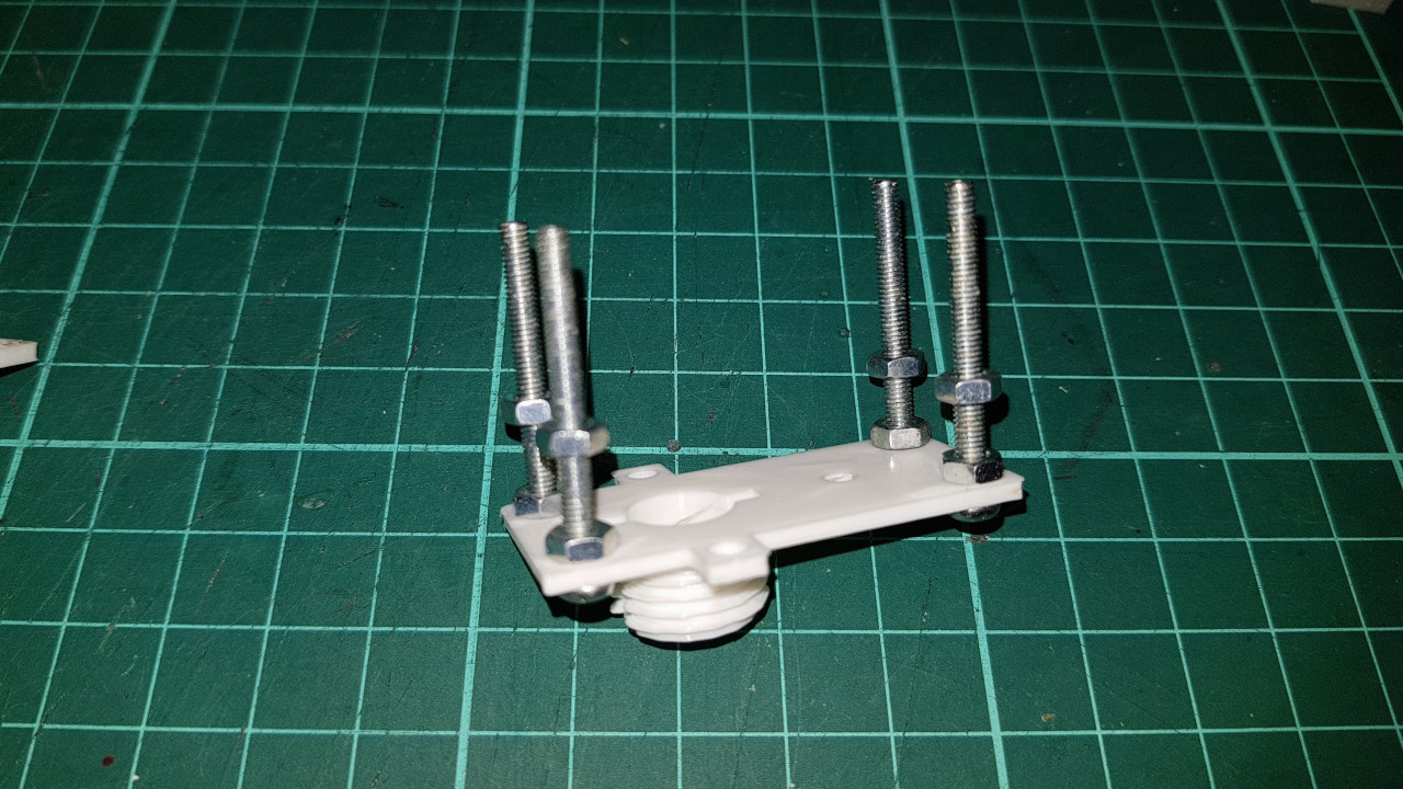
The outer shaft should then be inserted to through the upper plate. Align the tabs through the holes in the plate so that it may slide through.
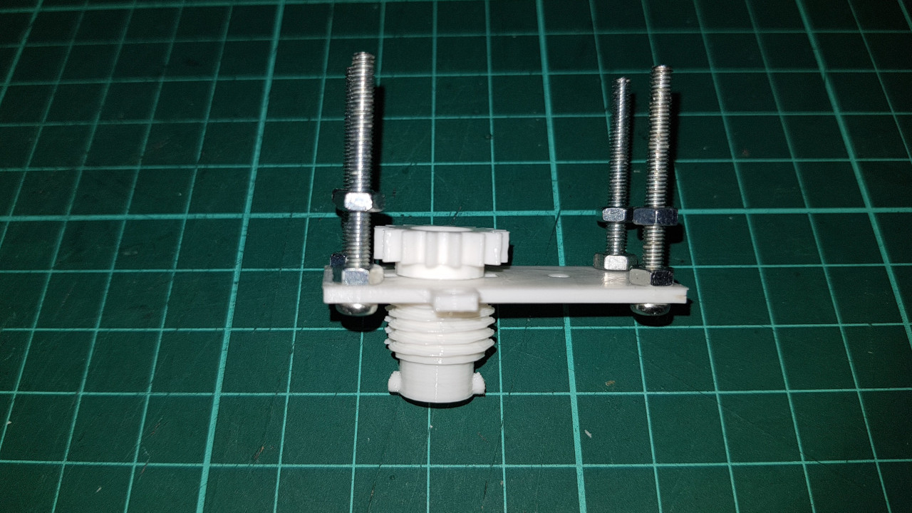
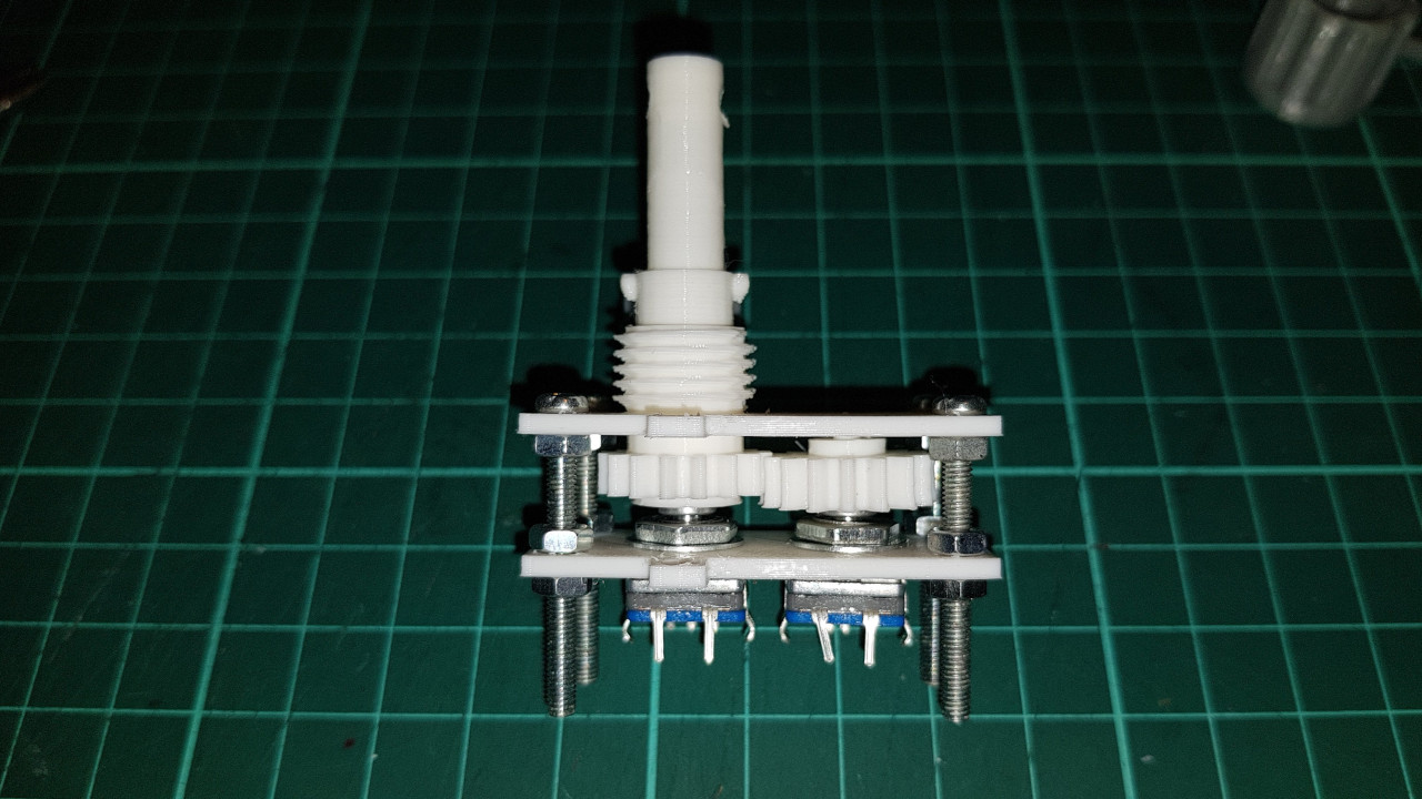
Connect the upper and lower plates together, making sure the two cogs align properly. Once the upper and lower plates are aligned, adjust the middle nuts so they touch the lower plate. Insert four more nuts to secure the lower plate. You should be able to feel a click when you press down on the inner shaft. If not, increase the spacing between the plates.
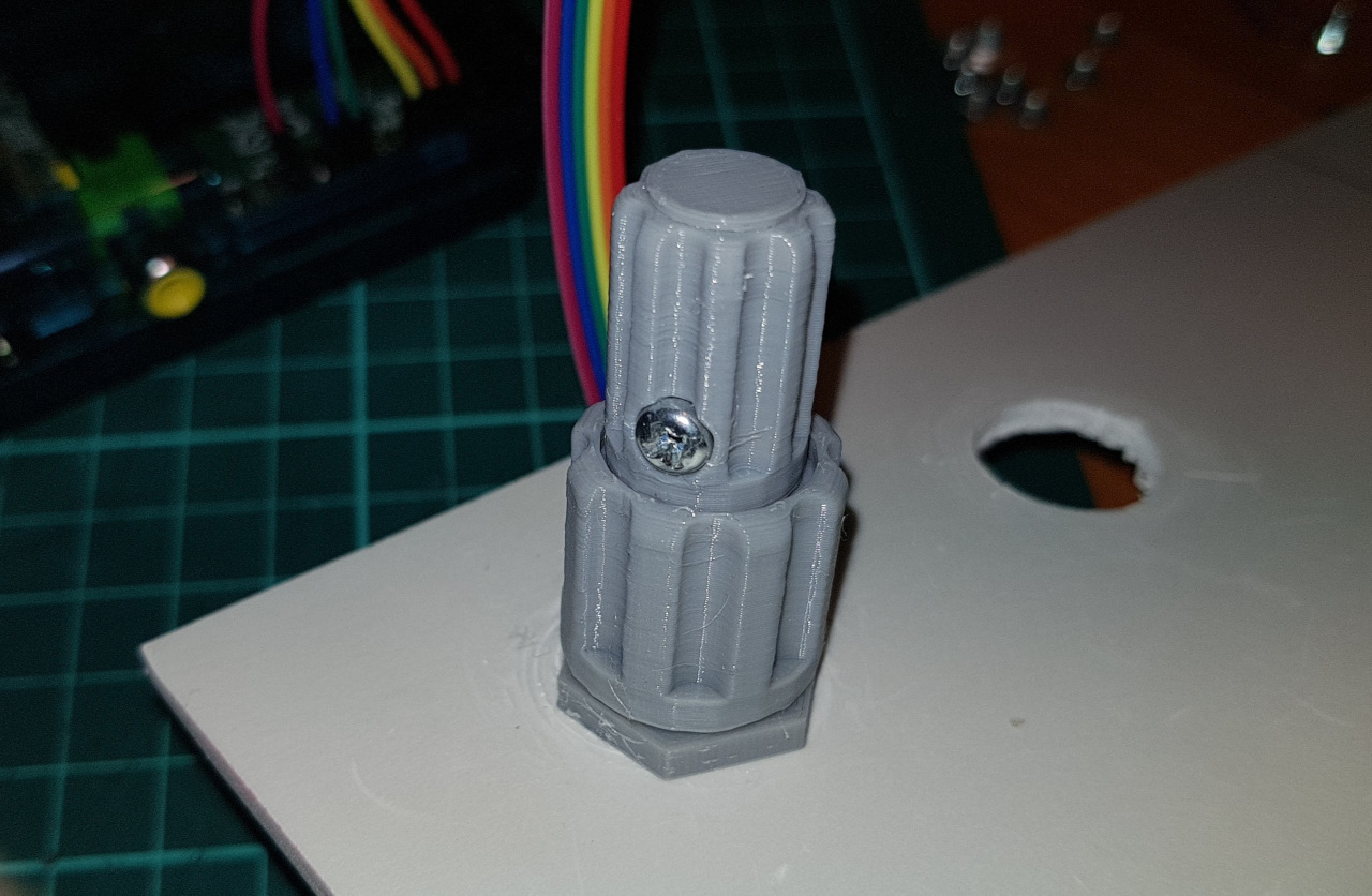
Panel Mounting
The part is designed to be mounted onto a 3mm thick panel. For this method, you will need a 16mm hole drilled into your panel. I used a 16mm hole saw to create this. The part is simply placed through the hole and tightened using the mounting nut. In my case, it was sufficiently tight to hold the part in place, however you may wish to use hot glue to further secure the part in place.
If the mounting nut doesn’t work for you, or if you have a thicker panel, you can also mount the part using two m3 bolts. Use the lower plate as a template and drill additional holes on your panel where the “tabs” are. Then use these two holes to mount the part in place. By using longer bolts, you can also place the part further away to the back of the the panel, which is useful of you have other clearance issues with other components on the panel. When extending the part further behind the panel, you may need to extend the Outer shaft and inner shaft lengths. Just ungroup the part in tinkerCAD, extend them accordingly, and regroup the parts together.
Once mounted to your panel, align the groves in the outer knob with the tabs on the outer shaft, and slide the knob down.
The inner knob is secured into place using a M3x12 bolt. You will first need to tap a M3 thread into the hole on the inner shaft, using a M3 Tapping Bit. When fixing the M3x12 bolt in place, do not overtighten or you will damage the thread.
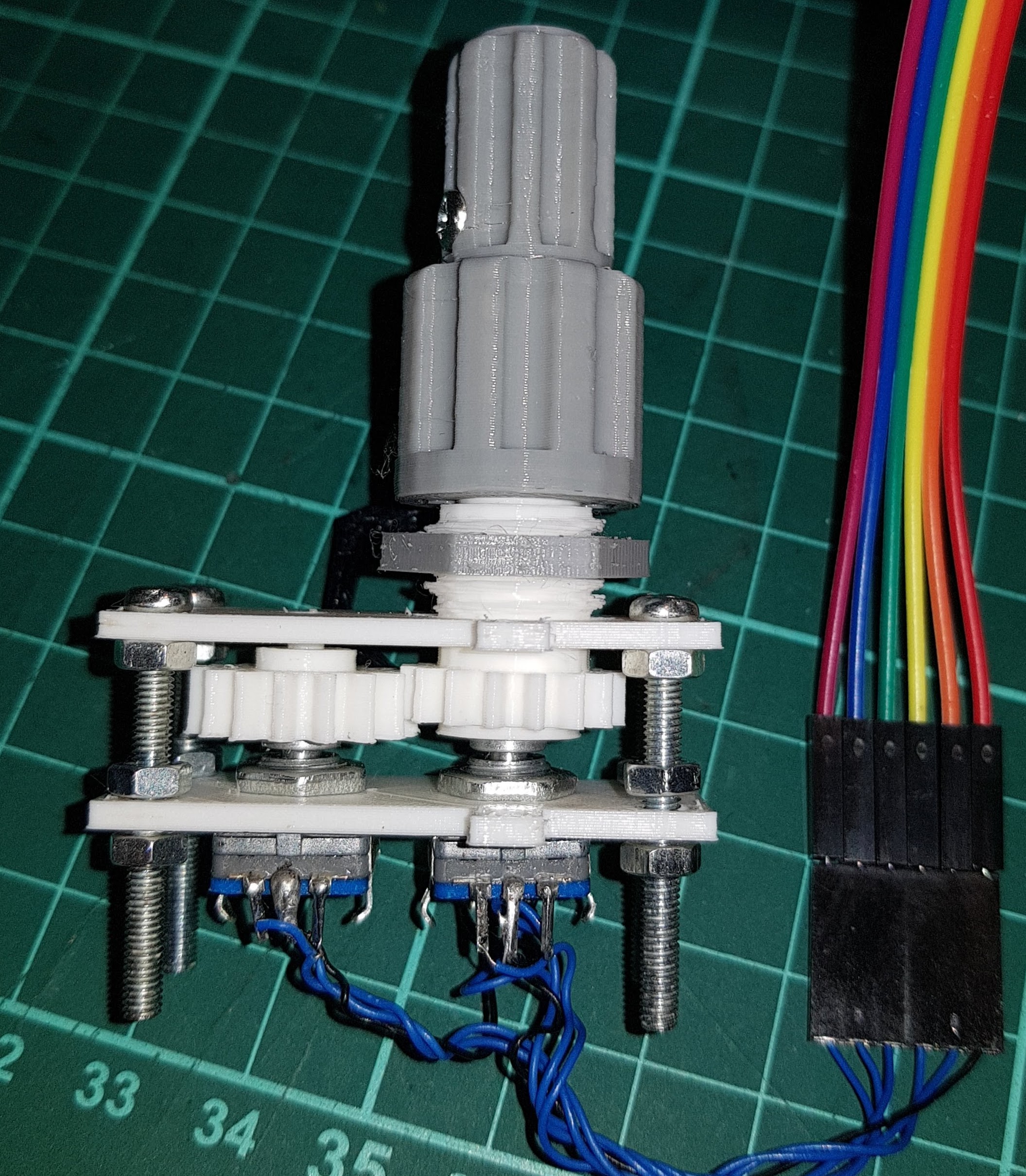
Wiring
The pins on the part are as follows:
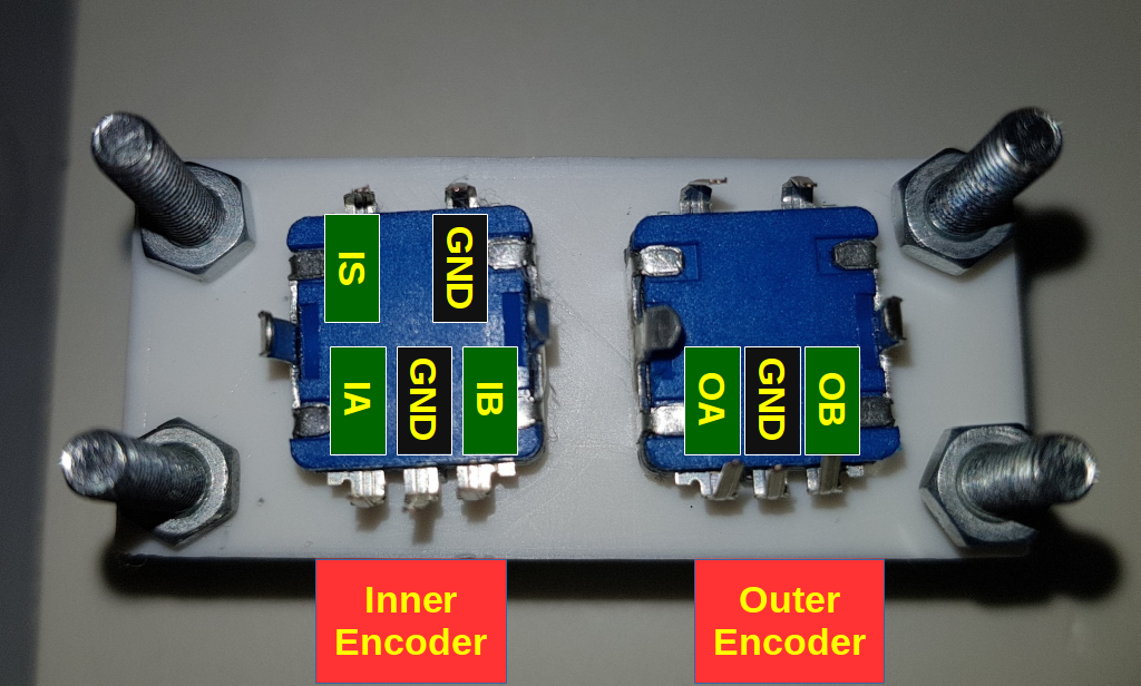
- GND – Signal Ground
- IA/IB – Rotation Signals for Inner Encoder
- OA/OB – Rotation Signals for Outer Encoder
- IS – Push button Switch for Inner Encoder
We don’t need to use the push button Switch for the Outer Encoder since it’s not possible to press it mechanically. The other two tabs at the sides are for mounting the rotary encoders to a PCB and not used in this design.
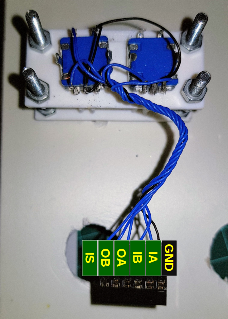
Start by soldering wires and bridging the four GND points together. You can then either solder wires to attach to attach the signal wires directly to your controller, or solder wires to attach a DuPont 6-way connector (see my post on crimping DuPont pins). If you use a connector, I suggest the following pin layout:
Decoding A Rotary Encoder
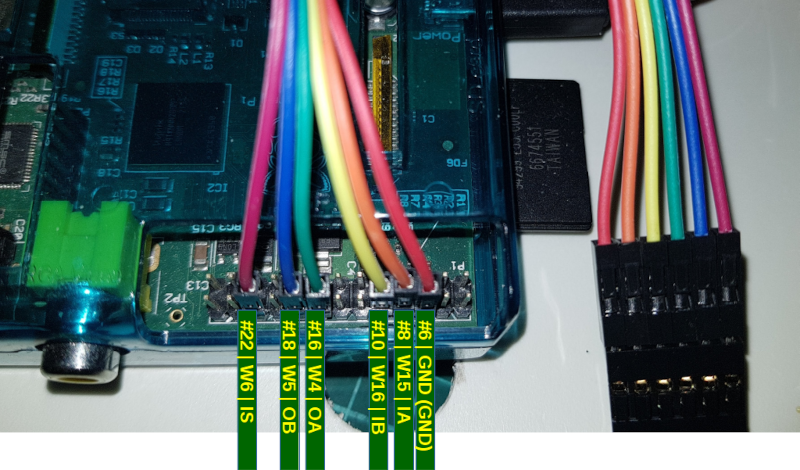
To demonstrate the part, I connected it to a Raspberry Pi, and wrote a test program using the WiringPi library. I connected the wires to my Pi Model B’s GPIO Pins as follows:
Notes:
- This my original Model B with 26 GPIO pins. On a newer Pi Model B+, 2, or 3, with 40-pin GPIO, the pin connections are the same, except that there are extra pins (27-40) on the left.
- Pins #8 and #10 are shared for use with the TTL Serial Port. Make sure this is disabled (using “sudo raspi-config”).
In our program, after calling wiringPiSetup(), the pins in use are configured as inputs, using the pinMode() command.
The rotary encoder signals by transitioning between a “not connected” state to “connected to ground” state. To read this using our GPIO inputs, we need to enable the built-in pull up resistor on the raspberry pi. This will cause the GPIO to return “1” (high) when the line is not connected to ground, and “0” (low) when the line is connected to ground.
Next let us look at the signalling mechanism of this rotary encoder. Not all rotary encoders work the same way, but almost all of the cheap “no-name” ones do.
In these rotary encoders, whenever the knob is “idle” in a detent, both signal lines A and B will report 1.
When the encoder is rotated to clockwise a single “click”, the following transition is observed:
|
|
A
|
B
|
|
(Idle)
|
1
|
1
|
|
Start
|
0
|
1
|
|
|
0
|
0
|
|
|
1
|
0
|
|
Finish (Idle)
|
1
|
1
|
A single Clockwise “click”
And when the encoder is rotated anti-clockwise a single “click”, the following transition is observed:
|
|
A
|
B
|
|
(Idle)
|
1
|
1
|
|
Start
|
1
|
0
|
|
|
0
|
0
|
|
|
0
|
1
|
|
Finish (Idle)
|
1
|
1
|
A single Anti-clockwise “click”
A few observations can be made from these two tables:
- For each click in either direction, four transitions occur.
- We can tell when an encoder is idle, because at that point A = 1 and B = 1
- When the first transition that brings the encoder out of idle occurs, we can identify the direction the knob is being rotated in by looking at which signal changed first to 0 (A = 0 means clockwise, B = 0 means anti-clockwise).
- Everything else can be ignored until we are idle again (A = 1 and B = 1).
Because the exact sequence of transitions is critical, it is critical that our program is aware of every change in transition as it occurs. Fortunately, the wiringPi library allows us to use interrupts to call our code when a transition occurs on a GPIO line.
Using interrupts is superior to frequently checking the status of A and B, which may result in reading the situation wrongly if a signal changes state when we are not looking. Using interrupts also has the advantage of not using the CPU unnecessarily.
To tell wiringPi to call our code when an interrupt occurs, we need to declare an Interrupt Service Routine (ISR). The WiringPiISR() command takes a pin number, a transition mode, and a pointer to the ISR function. The transition mode can be INT_MODE_FALLING, INT_MODE_RISING, or INT_MODE_BOTH, and determines whether the ISR should be called when the signal transitions from 1 to 0 (falling) or 0 to 1 (rising) or both. Since we are interested in both rising and falling transitions, we use INT_EDGE_BOTH.
Because we have two encoders, and wiringPi’s wiringPiISR() command doesn’t allow us to pass parameters to the ISR, we need two separate ISRs for each encoder.
Each ISR maintains a boolean variable called encoder_I_idle, which tracks the whether the encoder is in an idle position or not. When the ISR is called, the current value of pin A and B are read. If the encoder was idle before this, it means that this is the first transition within the click, and we can check whether pin A or pin B is 0, to determine the direction. Otherwise, it means we are somewhere in the middle of a click and therefore the current transitions are of no interest. The ISR finally checks if both A and B are 1 (which signifies the end of a click) and sets the encoder_I_idle variable accordingly, to prepare us for the next transition.
The above logic is all we need to handle the rotary encoders.
For the push button switch, it is a simpler situation, as there is only one signal. We just need to wait for a FALLING transition to determine when the button has been pressed (we don’t really care when the button is released). A separate ISR is used to service the push button.
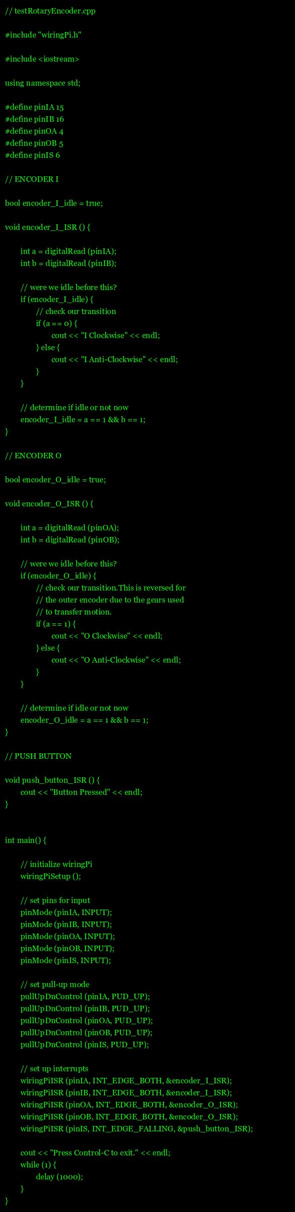
At this point, our test program to read both rotary encoders and the push button looks like this:
And Now for Some In-Flight Entertainment
A practical use of the Dual Concentric Rotary Encoder with Push Button is to act as a radio tuner within a flight simulator.
I’ve expanded the test program above and added in some code that opens a connection to an X-Plane simulator with the ExtPlane plugin installed. If you open any aircraft with the Laminar X1000 avionics suite (for example, the Cessna 172 with G1000 or the Cirrus), the Dual Cocentric Rotary Encoder can be used to tune the COM1 and COM2 radios. The outer encoder tunes the integer portion of the frequency, and the inner encoder tunes the decimals. Pressing the push-button toggles between COM1 and COM2.
The way this works is that within the ISR routine, I’ve added calls that submit commands to the ExtPlane service. These commands can be used to control many aspects of the flight simulator.
Here’s the demo in action:
https://youtu.be/mXS_wEJCNN8
The source code for the demo is available here: https://github.com/dotsha747/TestRotaryEncoder. To run it, clone the repository and type “make”. You will need to have my libXPlane-ExtPlane-Client libraries installed (see here for instructions). To start the demo, just execute “./testRotaryEncoder <IP>”, where <IP> is the IP address of your X-Plane PC.
#X-Plane #g1000
Originally created with EverNote at 20180218T213348Z